Bottom Camera Position (Video Guide)
Now that we know the offset from the top camera to the nozzle, we can use the nozzle to set our bottom camera position.
-
Navigate to
Machine Setup > Cameras > OpenPnpCaptureCamera Bottom.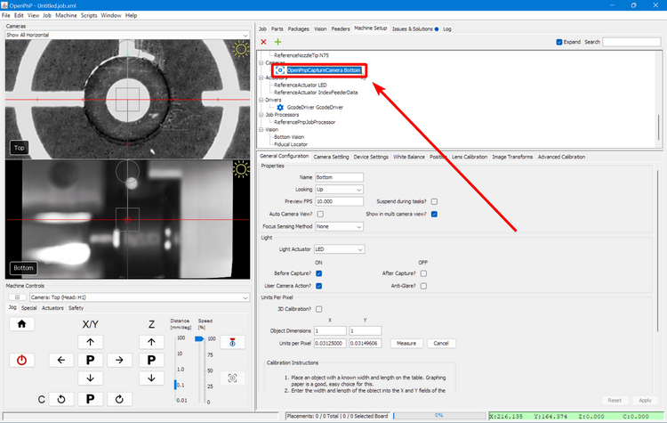
-
Click on the
Positiontab.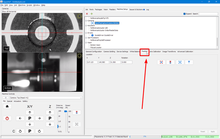
-
Select the
Nozzle: N1from the machine controls dropdown.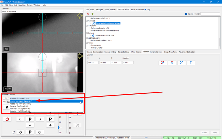
-
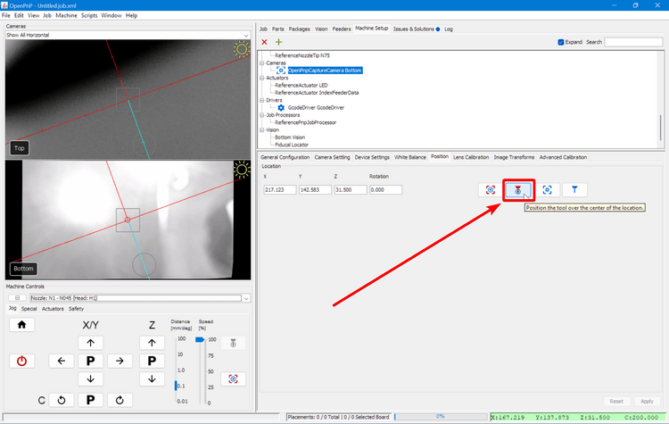
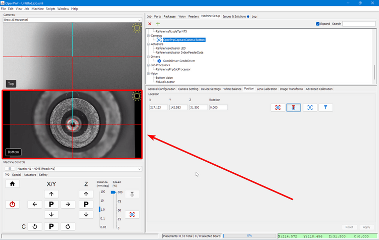
Click the "Position tool over location" button to bring the left nozzle roughly above the bottom camera.
-
Jog the toolhead until the left nozzle is directly in the center of the bottom camera's vision.
-
Click the "Capture Toolhead Location" button to calculate the correct position for the bottom camera. Make sure your Z height is at 31.5. If it isn't, manually enter
31.5into the Z field.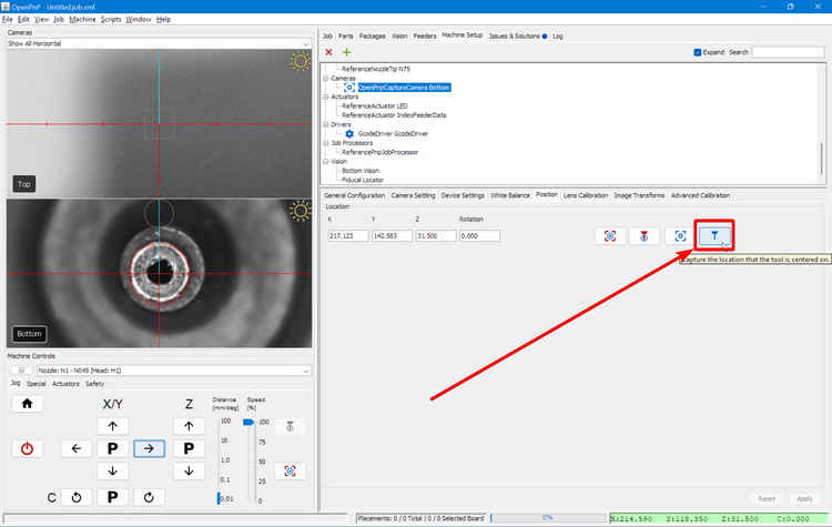
-
Click the
Applybutton to save the new camera position.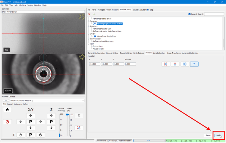
Next Steps
Next is Nozzle Tip Calibration.