Mounting the Motherboard
Mounting
| Qty | Part |
|---|---|
| 4 | M3 25mm Standoff |
| 8 | M3x8 machine screw |
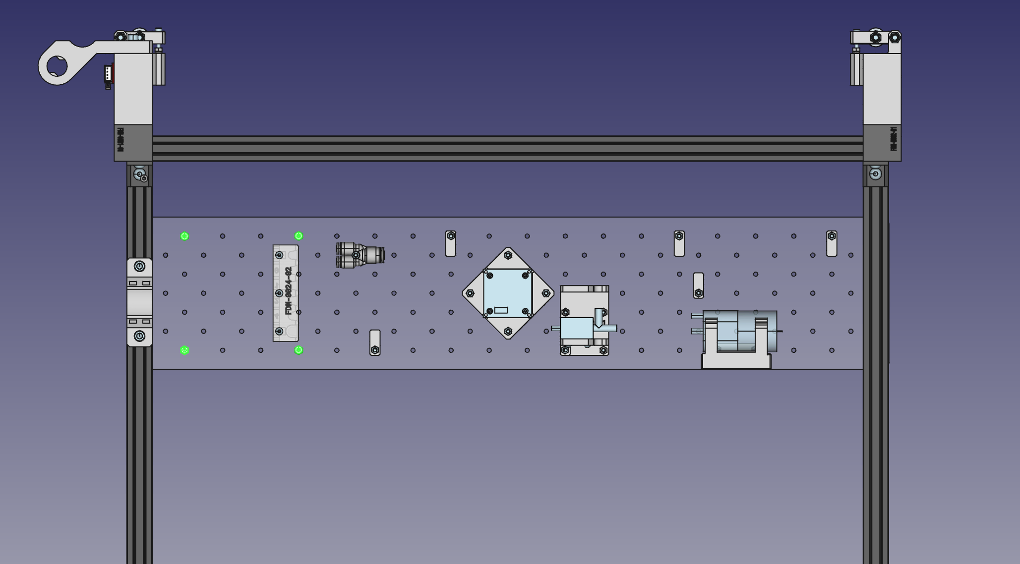
Now that we've got all the THT components soldered in, it's time to mount the motherboard to the staging plate. It's important to make sure we're mounting the motherboard in the correct place on the staging plate so that all the cables fit and reach their respective ports correctly.
-
Put your Lumen up on its haunches and take a look at the left side of the staging plate. We will be working with the following holes on the staging plate: A3, G3, A9, G9.
-
Pass four M3x10mm screws through the top side of the staging plate, and tighten them into the standoffs. !Standoffs Installed](images/IMG_0716.webp)
-
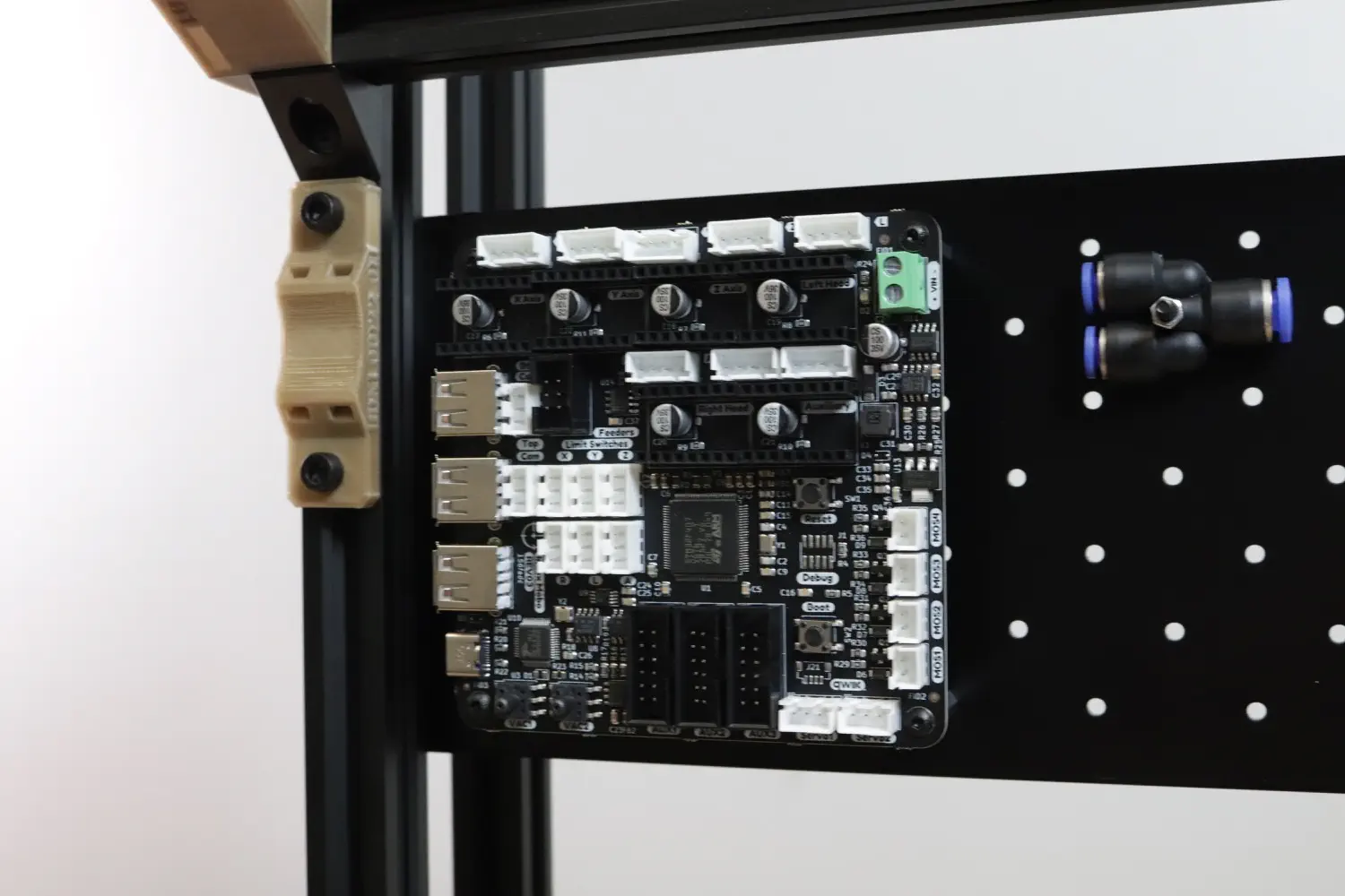
Now we can mount the motherboard itself. Confirm the orientation of your motherboard so that the USB ports are facing to the left and the vacuum sensors on the bottom. Then use four M3x10mm screws to secure the motherboard to the standoffs.
Drivers
| Qty | Part |
|---|---|
| 4 | Stepper motor driver PCB |
| 4 | PCB Heatsink |
-
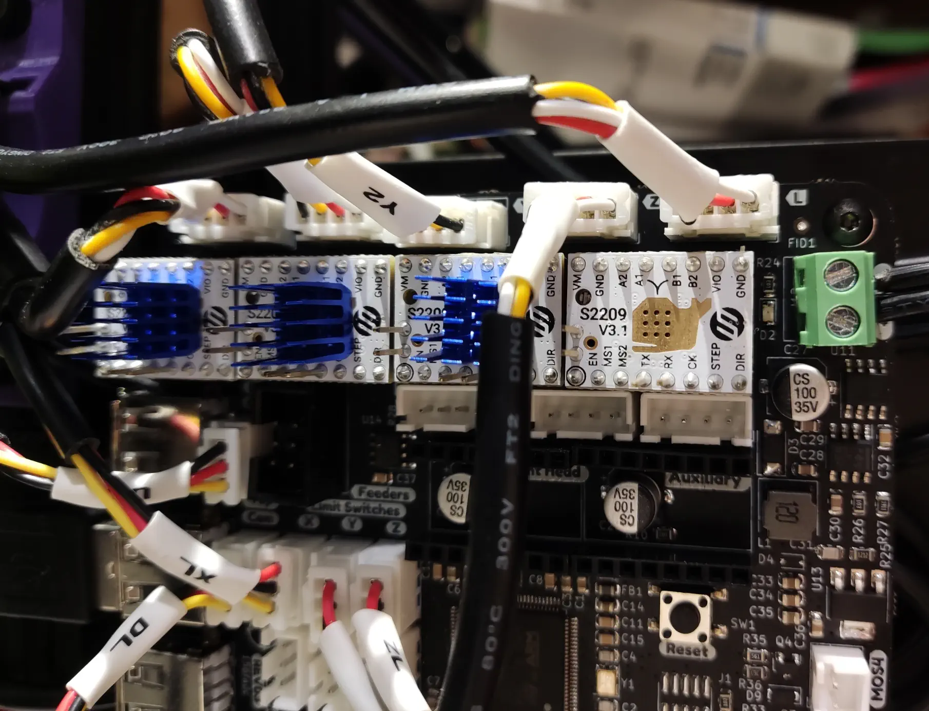
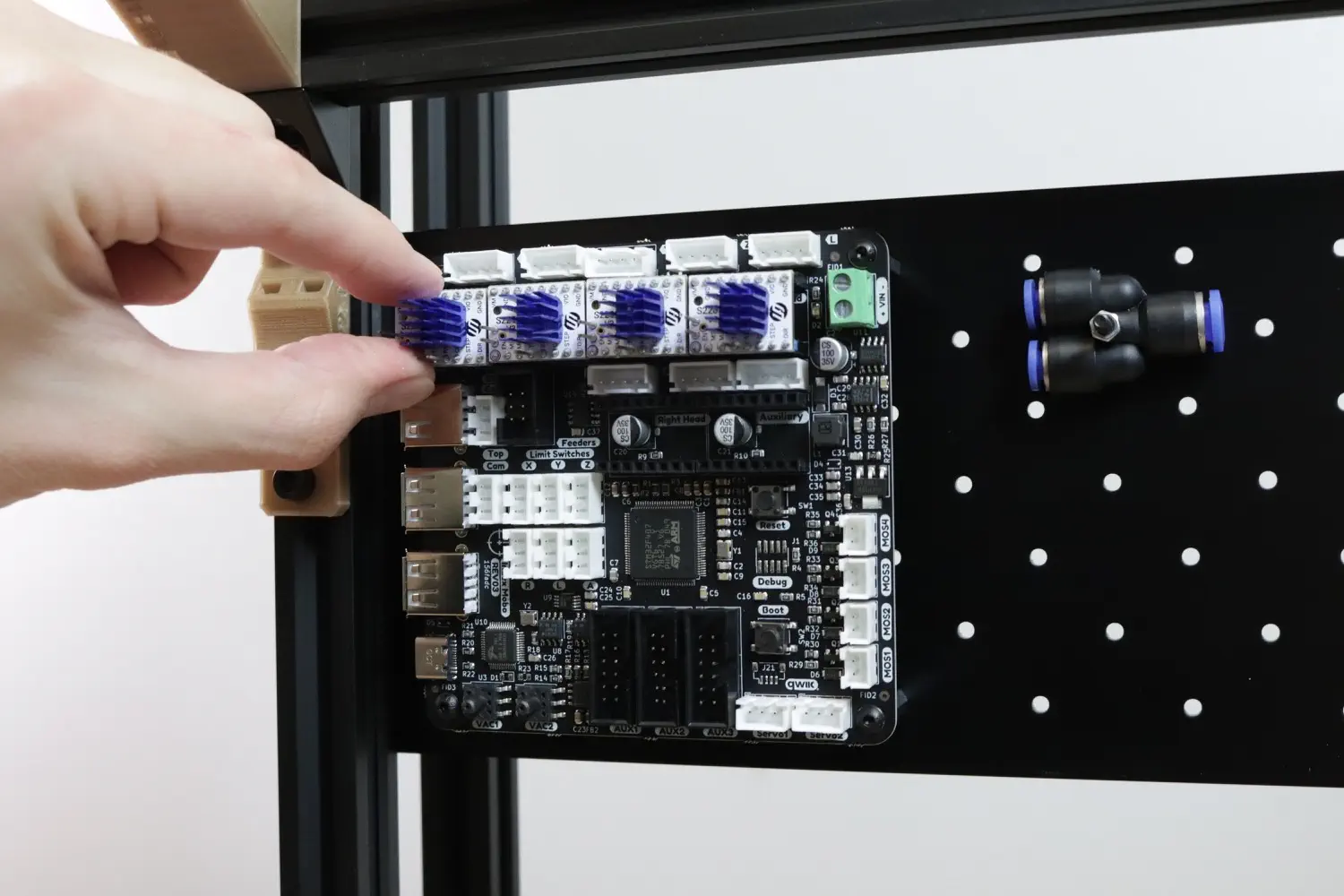
Install the four stepper motor drivers into the X, Y, Z, Left Head, and Right Head slots. Note that the whale icon on the motor drivers will be right-side up and the two upward-facing pins will be facing to the left.
-
Install the four heatsinks on the center of the motor drivers.
Note
It is very important to not plug in or unplug stepper motor drivers or motors while the board is powered on. Make sure to unplug the power supply before inserting or removing drivers or motors.
Power
| Qty | Part |
|---|---|
| 1 | Power Supply |
-
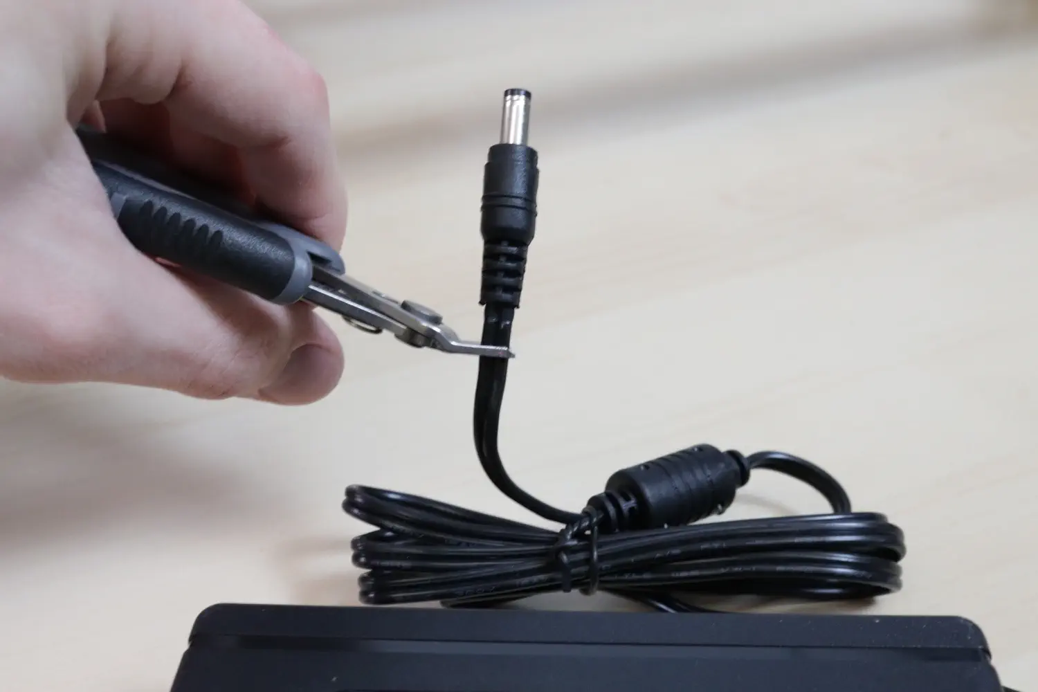
Cut the barrel connector off the end of the power supply cable.
-
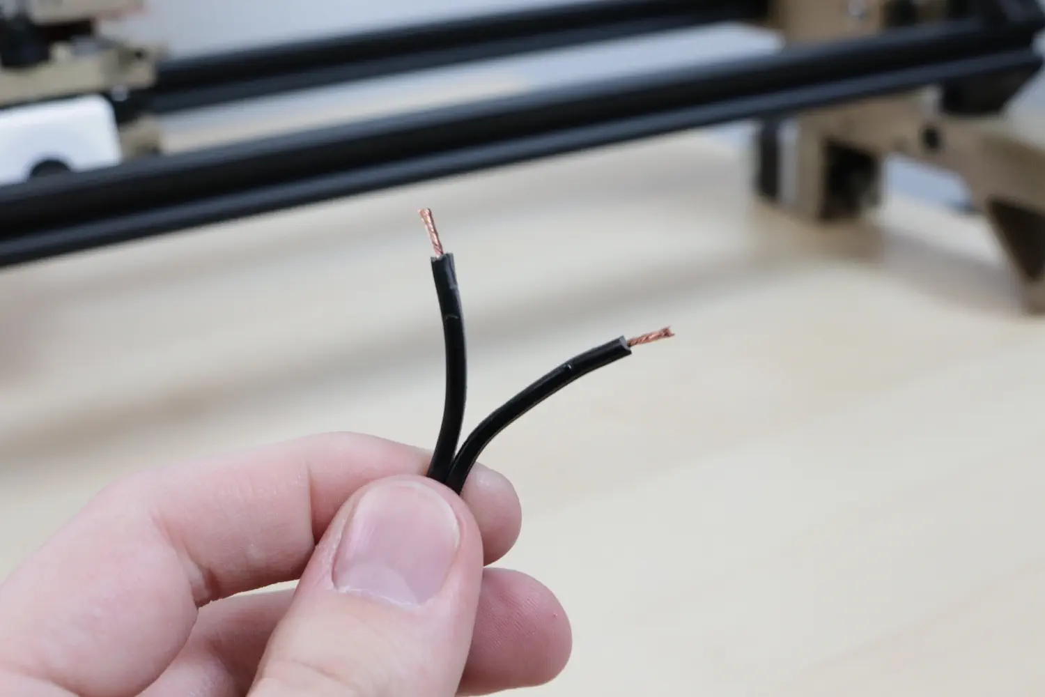
Separate the two wires and strip off the insulation of each.
-
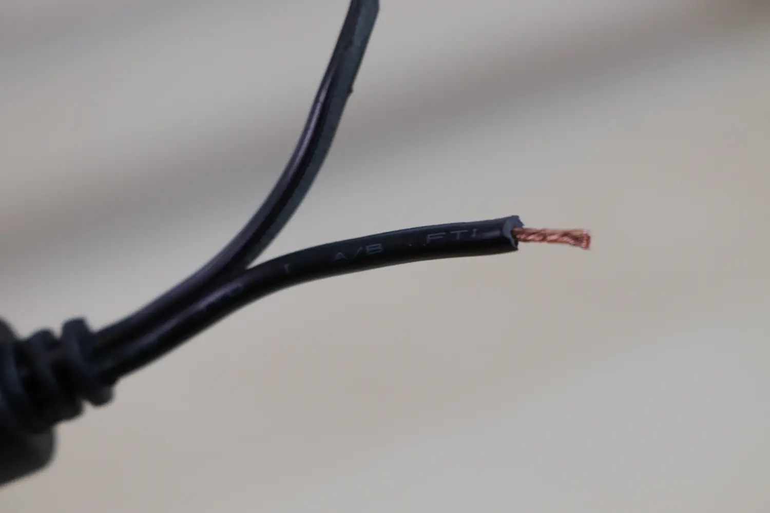
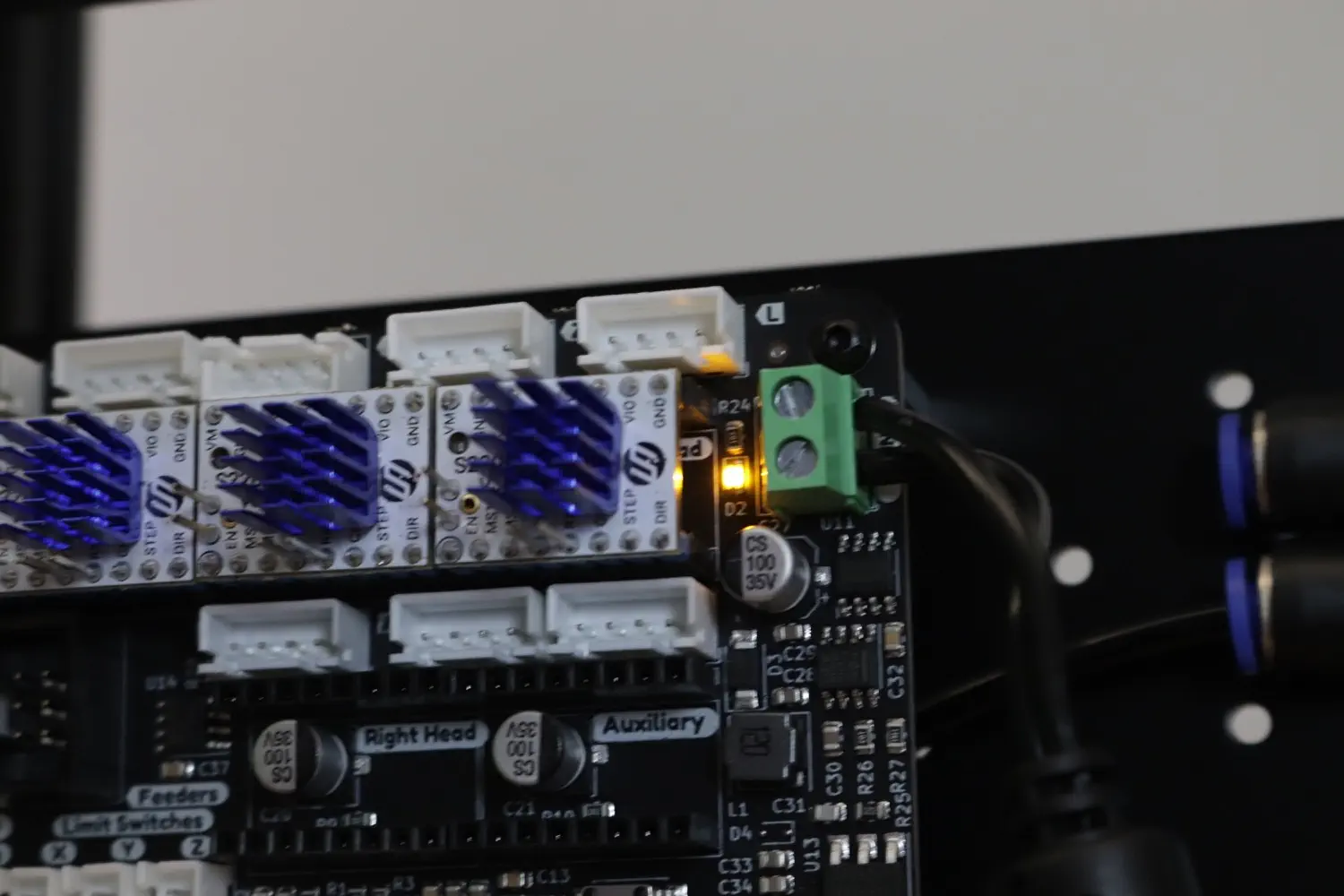
Twist the stranded copper and insert the wire with the white text into the positive side of the power screw terminal on the motherboard. Insert the black wire into the other terminal, and screw both down tightly.
Note
Do NOT apply solder to the twisted copper wires. This can prevent the wires from being compressed in the screw terminals, meaning uneven electricity and heat distribution and risk damaging your machine. You may use wire crimps if you prefer and have them on hand.
-
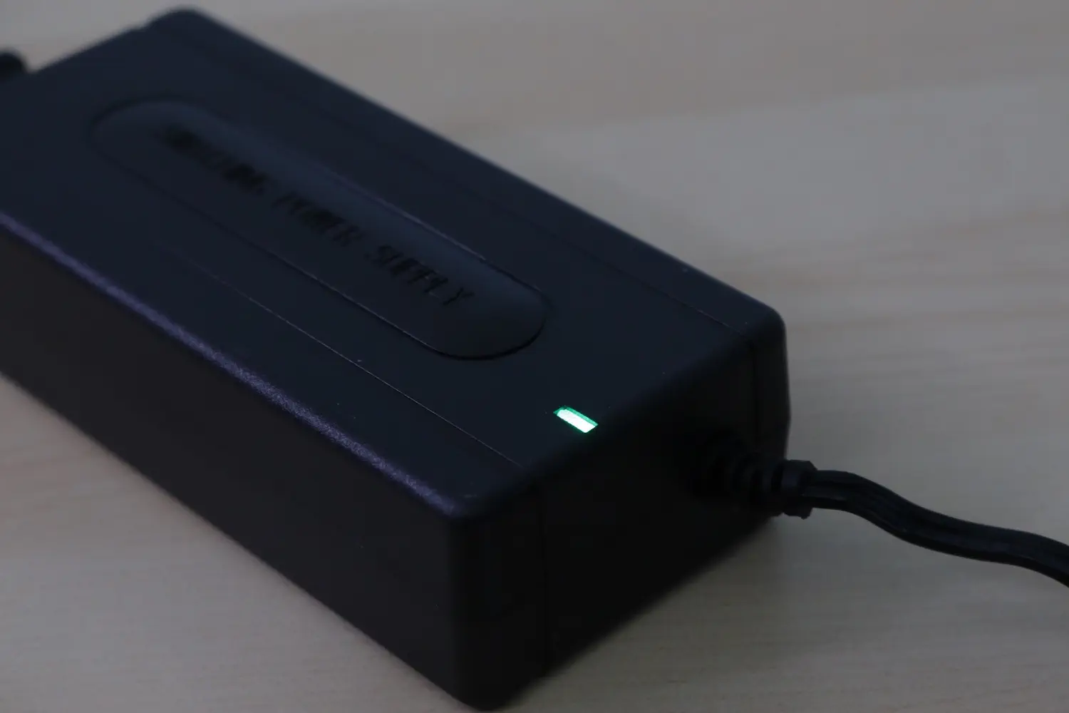
Next, plug in your power brick. Watch for a light by the screw terminal. If you do not see a light, check to make sure you inserted the wires into the correct terminals. Also check to see if the light on the power brick is illuminated. (The color of the light may differ based on which kit you received.)
Next steps
Continue to wiring and pneumatics.