Vacuum Part Detection (Video Guide)
While the bottom camera can detect if a part was successfully picked, you can use the LumenPnP's vacuum sensors to check for a successful pick a bit quicker. When a part is successfully picked it creates a seal at the end of the nozzle. This seal increases the vacuum pressure in the pneumatic line which is measured by the vacuum sensors. OpenPnP can use this increase in pressure to detect if a part was successfully picked.
Note
The LumenPnP v2 kit machine has different vacuum sensors than the v3 semi-assembled machine. Make sure to follow the steps for your machine version below.
LumenPnP v3
- Ensure there's still an N045 nozzle tip on the N1 nozzle.
-
Navigate to
Machine Setup > Nozzle Tips > ReferenceNozzleTip N045 > Part Detection.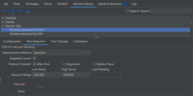
-
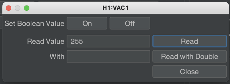
Open the
H1:VAC1actuator window. ClickOnto turn on your pump and valve, and then clickRead. You should see a value appear in theRead Valuetext box. Take note of this number.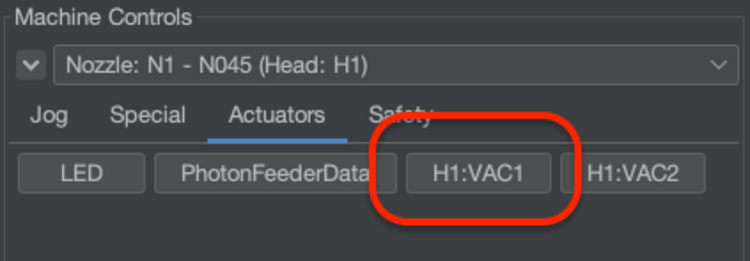
-
Now, cover the nozzle with your finger tip. Hit
Readagain. Take note of the new number. -
Split the difference between these numbers. For example, if your readings were
250and246, choose248. -
Enter this value into the
High Valuefield in theVacuum Rangesetting.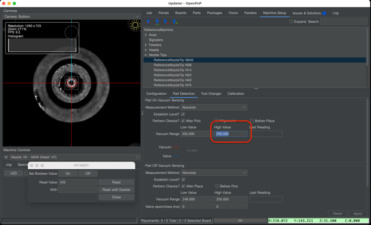
-
Perform this step again, but using N2 and the N24 nozzle tip.
LumenPnP v2
v2 Interposers
If you have a v2 machine, please check if you have interposer boards installed.
-
Select your GcodeDriver, then under the Gcode tab, select the
H1 VAC1actuator, and select theACTUATOR_READ_COMMANDsetting. -
Make sure the following Gcode is present in the field:
M3426 G2 C1 I1 A110Sensor Address
In the above code snippet, the line
M3426 G4 C1 I1 A110usesA110to specify which sensor to read from. Due to the way the sensors are programmed by their manufacturer, the address of the sensor can vary. IfA110doesn't work for you, try testing each binary value from0to7(eg000,001,010etc) to see which address is correct for your sensors. -
With the same
H1 VAC1actuator selected, now choose theACTUATOR_READ_REGEXsetting, and make sure the following is present in the field below:^.*V:(?<Value>\d+).* -
Select your GcodeDriver, then under the Gcode tab, select the
H1 VAC2actuator, and select theACTUATOR_READ_COMMANDsetting. Make sure the following Gcode is present in the field:M3426 G2 C2 I1 A110 -
With the same
H1 VAC2actuator selected, now choose theACTUATOR_READ_REGEXsetting, and make sure the following is present in the field below:^.*V:(?<Value>\d+).*
Next Steps
Next is the FTP.