Belt Tensioners
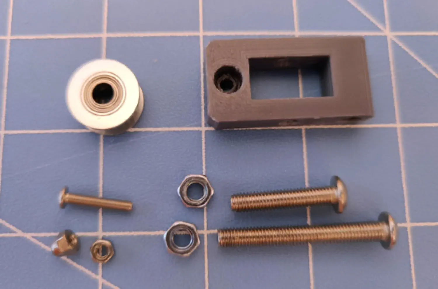
Alright, time to get into the build! First, we're going to build the belt tensioners that are used for the X and Y axes. You need to build three of these.
| Qty | Part |
|---|---|
| 1 each, 3 total | M3 Hex Nut |
| 1 each, 3 total | M3x16 machine screw |
| 1 each, 3 total | M3 Cap Nut |
| 1 each, 3 total | M5x25 machine screw |
| 1 each, 3 total | M5 Nyloc Hex Nut |
| 1 each, 3 total | M5x40 machine screw |
| 1 each, 3 total | M5 Hex Nut |
| 1 each, 3 total | GT2 Pulley Idler |
| 1 each, 3 total | FDM-0037 (Belt Tension Arm) |
| 1 | FDM-0001 (Front Left Leg) |
| 1 | FDM-0002 (Front Right Leg) |
| 1 | FDM-0013 (X Idler Mount) |
Assembling the Belt Tensioner Arms
-
Insert an M3 Hex Nut into its slot on the back of a
Belt Tension Arm.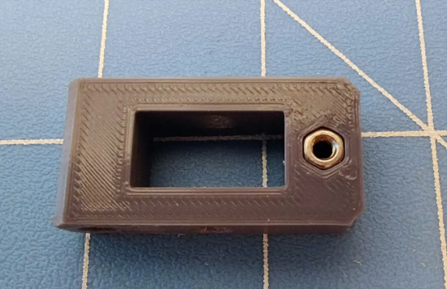
-
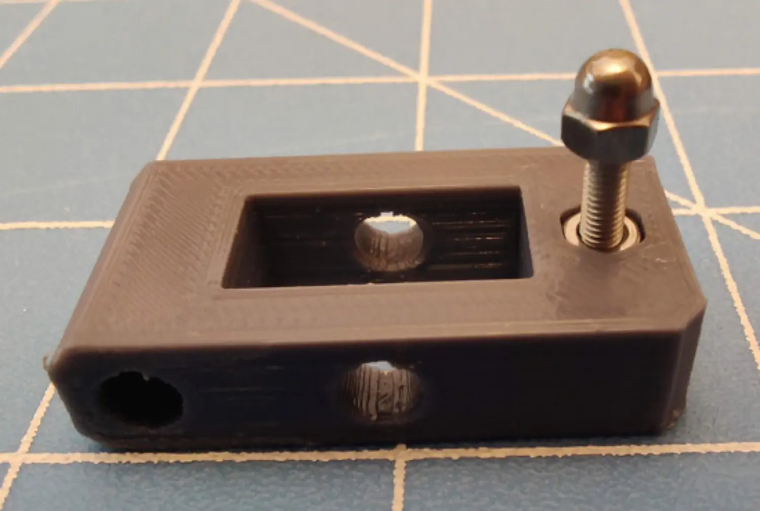
Insert an M3x16mm Machine Screw through the front hole in the
Belt Tension Armand then tighten.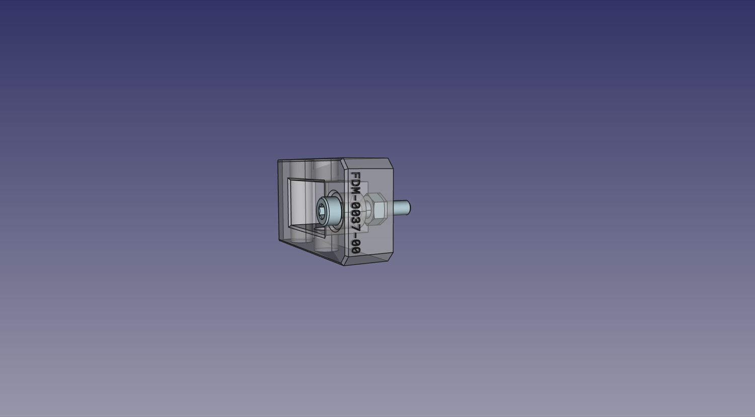
-
Thread an M3 Cap Nut on the end of the M3x16mm Machine Screw.
-
Insert an M5x25mm Machine Screw through the hole in the top of the
Belt Tension Armso that it passes through a GT2 Pulley Idler.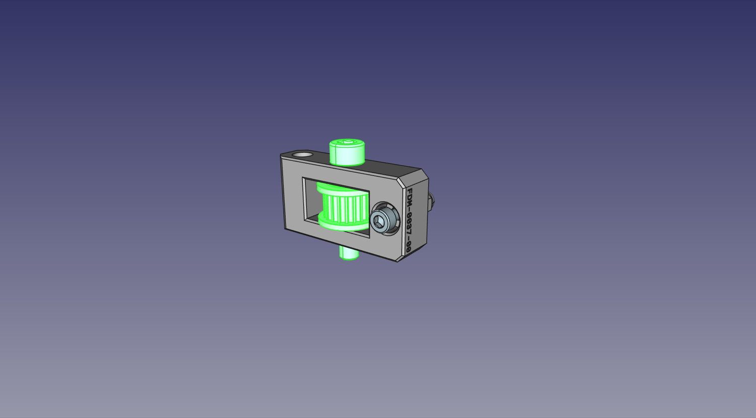
-
Add an M5 Nyloc Hex Nut on the bottom of the
Belt Tension Armand tighten. Make sure the idler can still spin freely.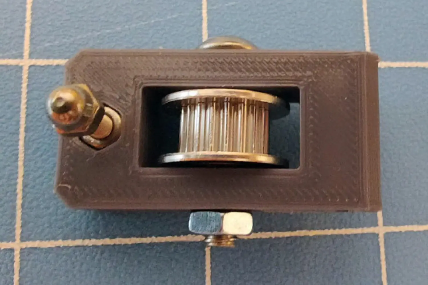
-
Repeat this two more times so that you have a total of three arms.
Attaching a tensioner to the left side
Now you'll attach the first tensioner to the Front Left Leg:
-
Insert an M5 Nyloc Hex Nut into the recess for a hex nut on the bottom of one of the idler mount arms on the
Front Left Leg.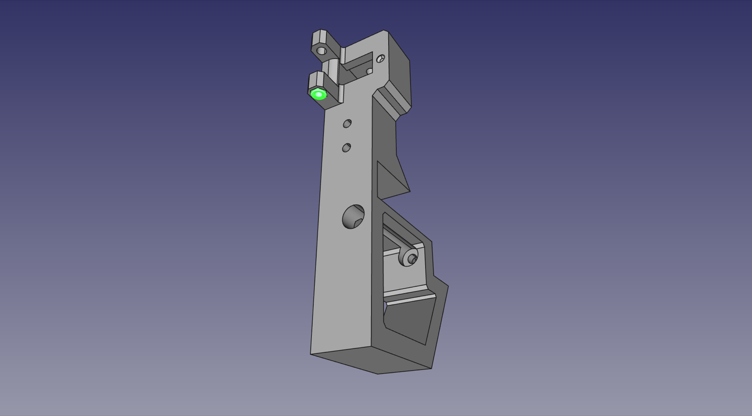
-
Insert a completed
Belt Tension Armassembly between the arms on theFront Left Leg, with the screw head of the M5x25mm facing up.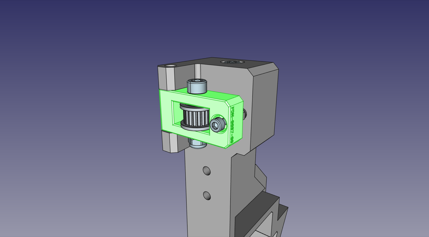
-
Insert an M5x40mm Machine Screw through the hole in the top so that it passes through the
Belt Tension Armand tightens into the M5 Nyloc Hex Nut. Do not over-tighten, and ensure you can still pivot the tension arm.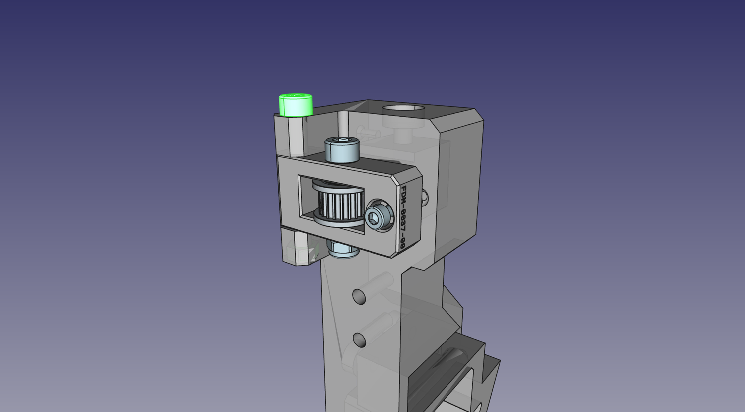

Attaching a tensioner to the right side
Next, attach the second tensioner the the Front Right Leg. This is nearly identical to the first one:
-
Insert the M5 Nyloc Hex Nut into the recess for a hex nut on the bottom of one of the idler mount arms on the
Front Right Leg.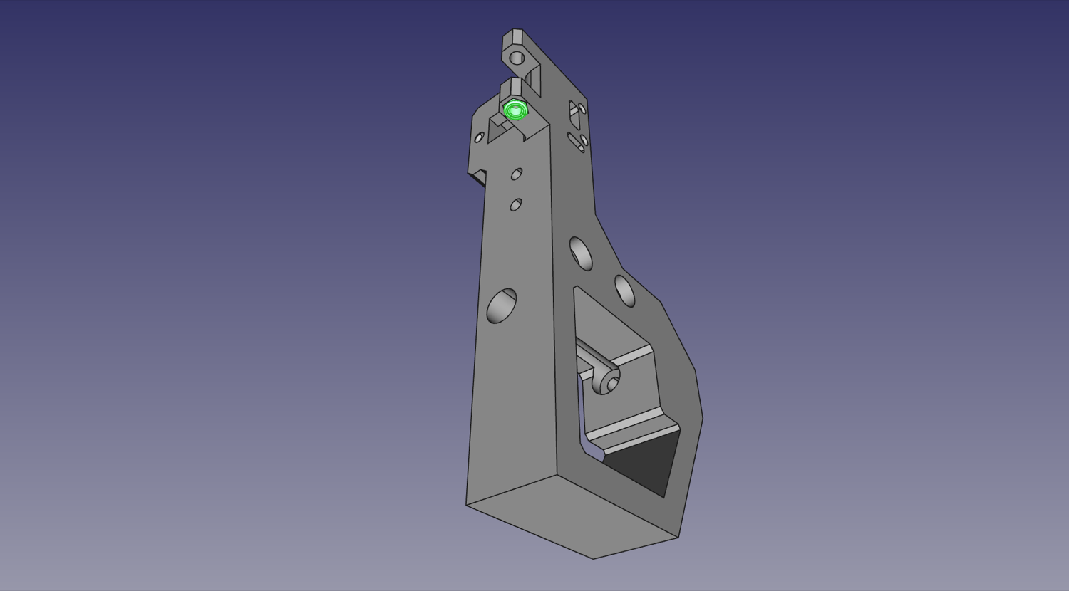
-
Insert a completed
Belt Tension Armassembly between the arms on theFront Right Leg, with the screw head of the M5x25mm facing up.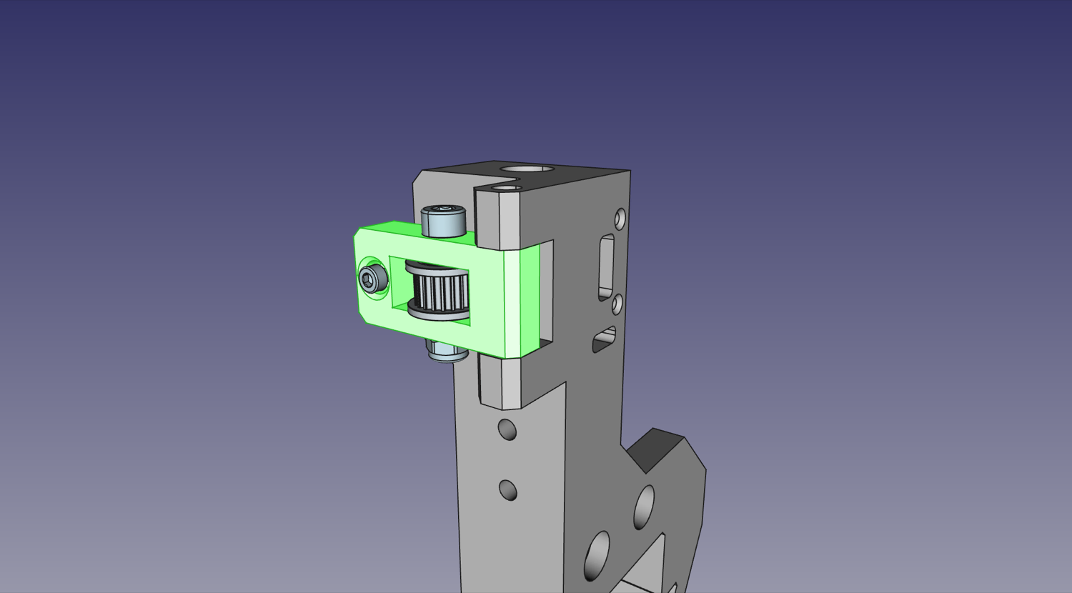
-
Insert the M5x40mm Machine Screw through the hole in the top so that it passes through the
Belt Tension Armand tighten into the M5 Nyloc Hex Nut. Do not over-tighten, and ensure you can still pivot the tension arm.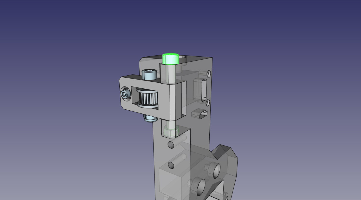
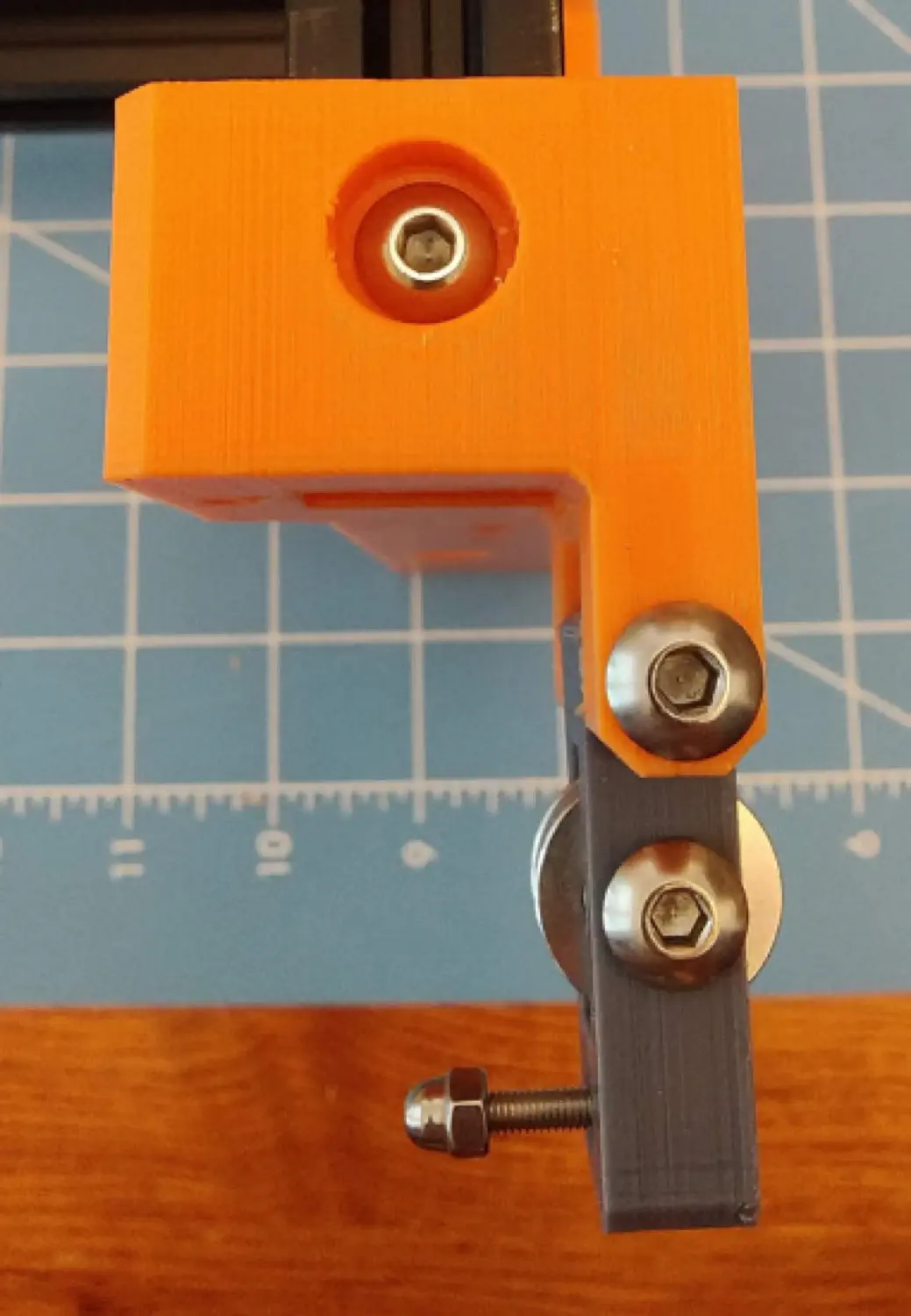
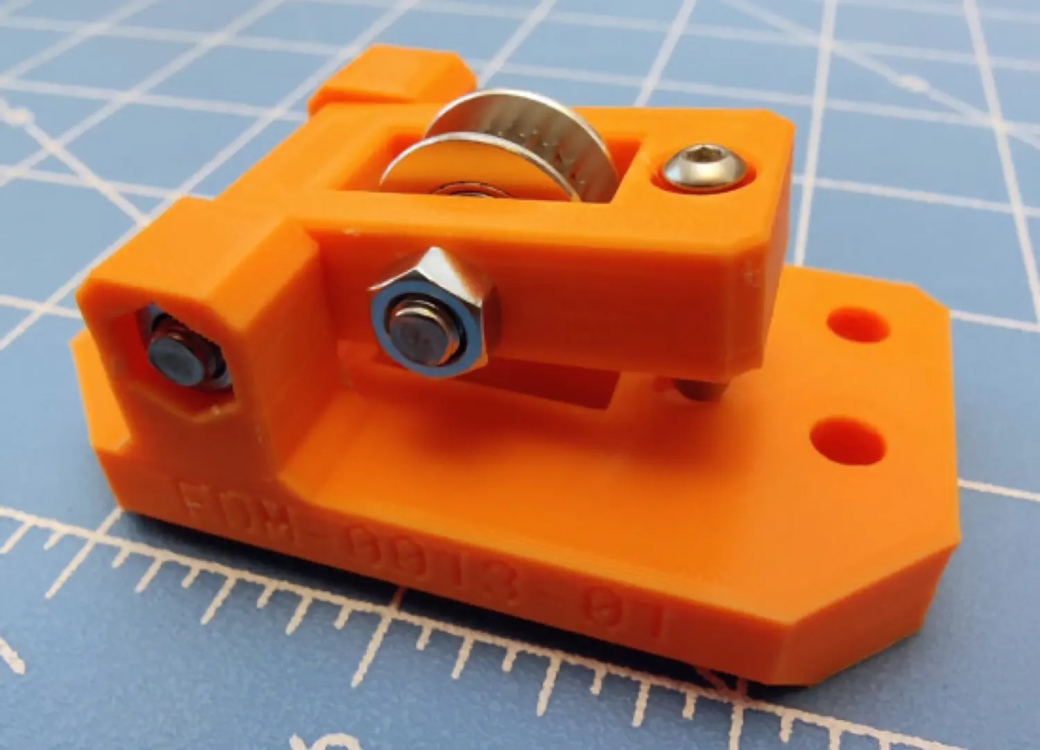
Attaching a tensioner to the X idler mount
The third and final tensioner is attached to the X Idler Mount. This is only slightly different from the previous two:
-
Insert the M5 Nyloc hex nut into the recess on the bottom of the
X Idler Mount.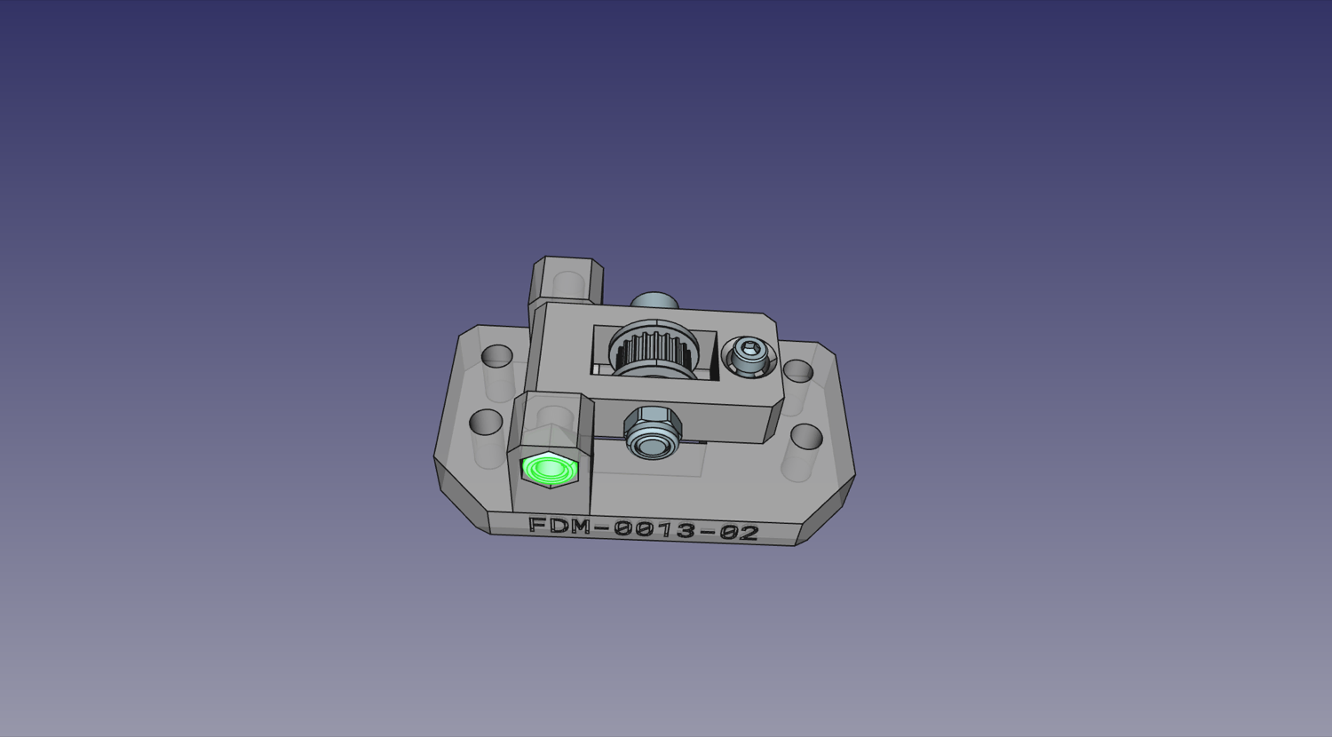
-
Insert the completed
Belt Tension Arminto its slot in theX Idler Mount.
-
Insert the M5x40mm machine screw through the hole in the top of the
X Idler Mountso that it passes through theBelt Tension Armand tightens into the Nyloc Hex Nut. Do not over-tighten, and ensure you can still pivot theBelt Tension Arm.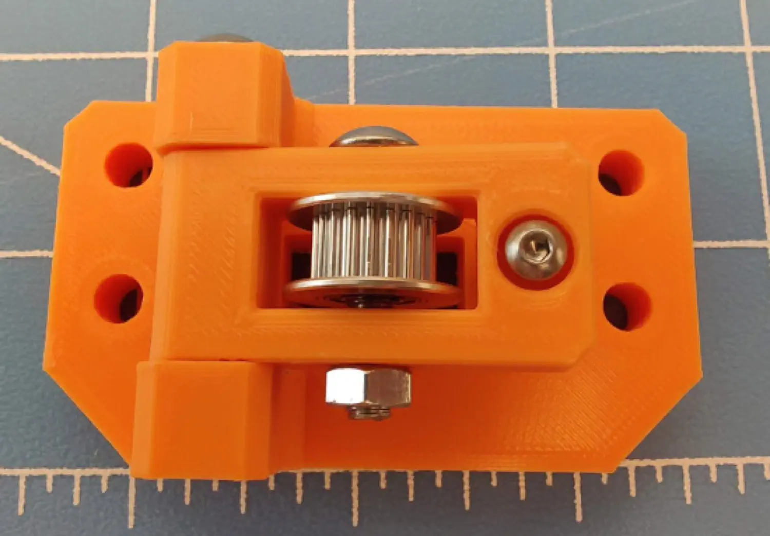
Next steps
Now that all the tensioners are in the right place, continue with assembling the left side.