Install THT Components
There are five types of connectors that need to be soldered into your motherboard. We'll go over each one, and how to solder them in place.
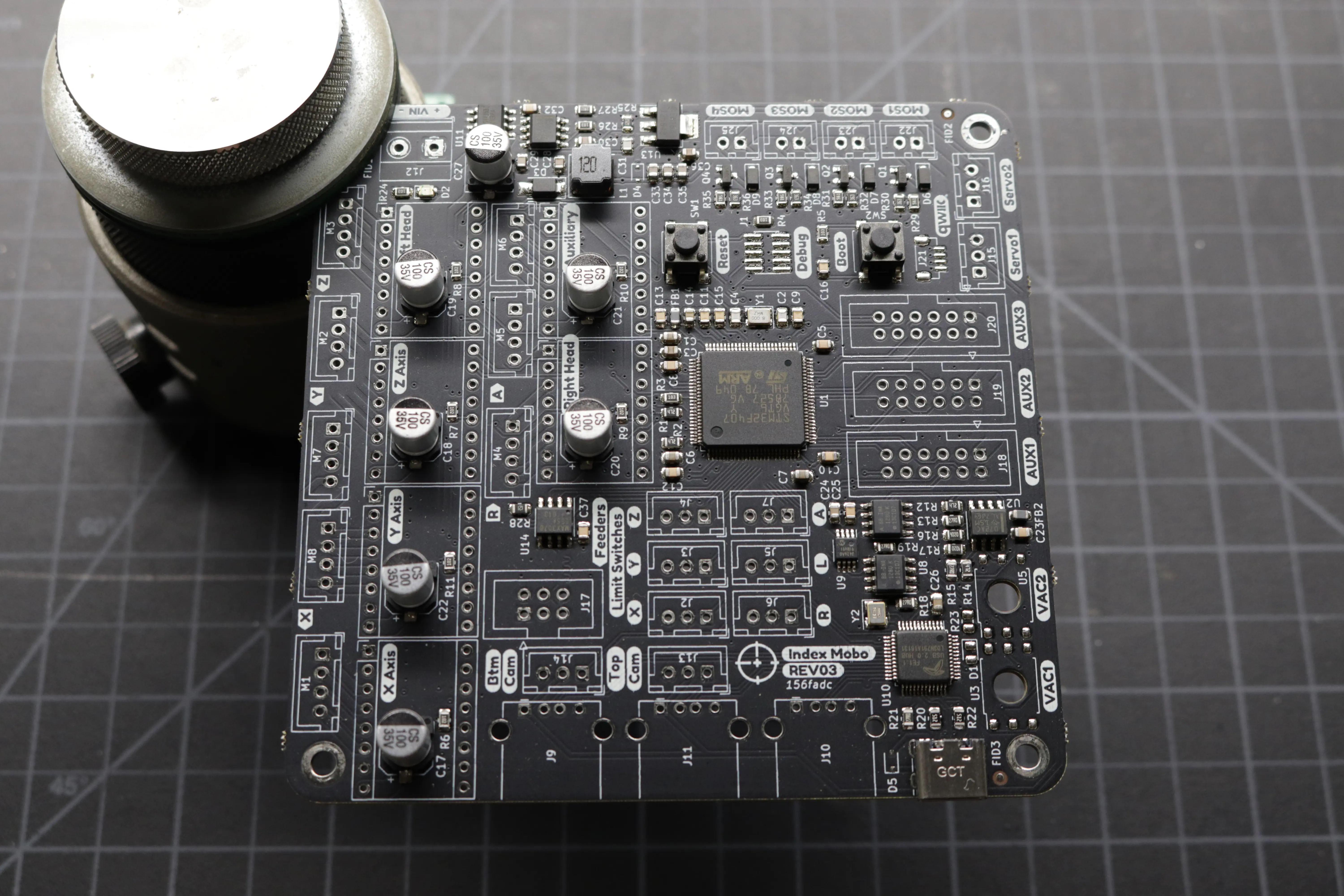
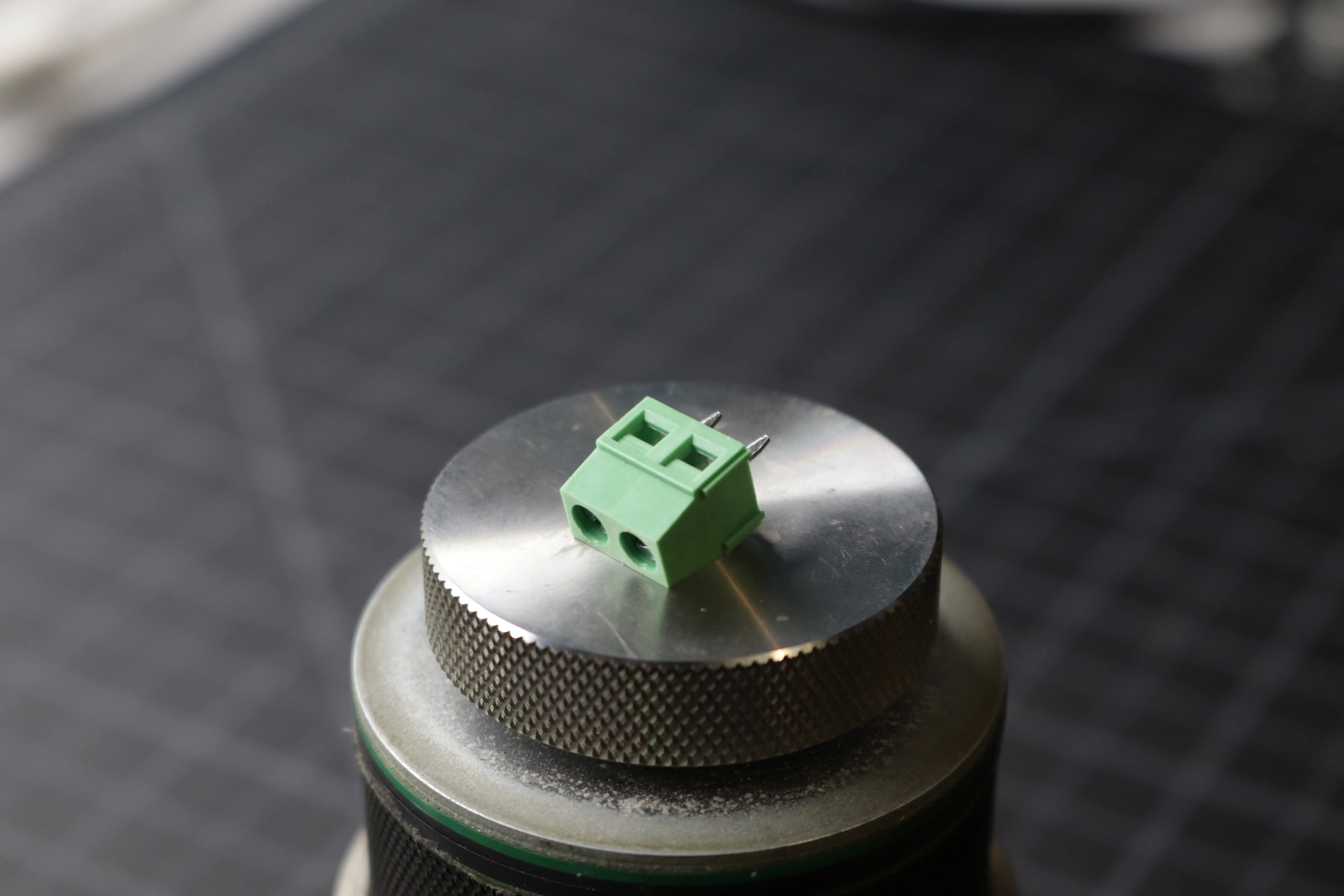
Screw Terminal
In your connector bag you'll find a screw terminal connector. This provides power to the machine, and goes into the J12 footprint on the upper-right corner of the board. Ensure that the openings that accept the power cables are facing outwards.
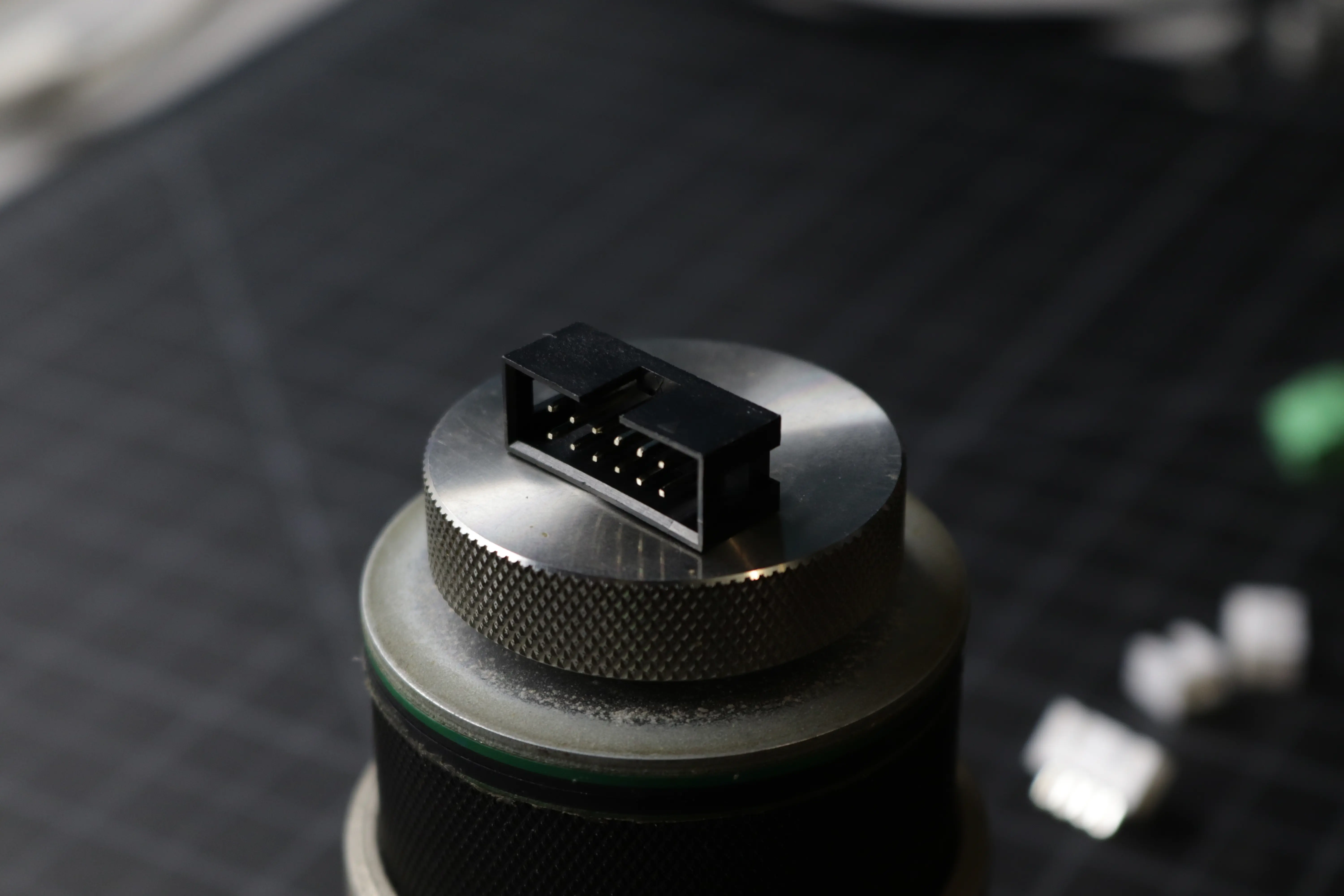
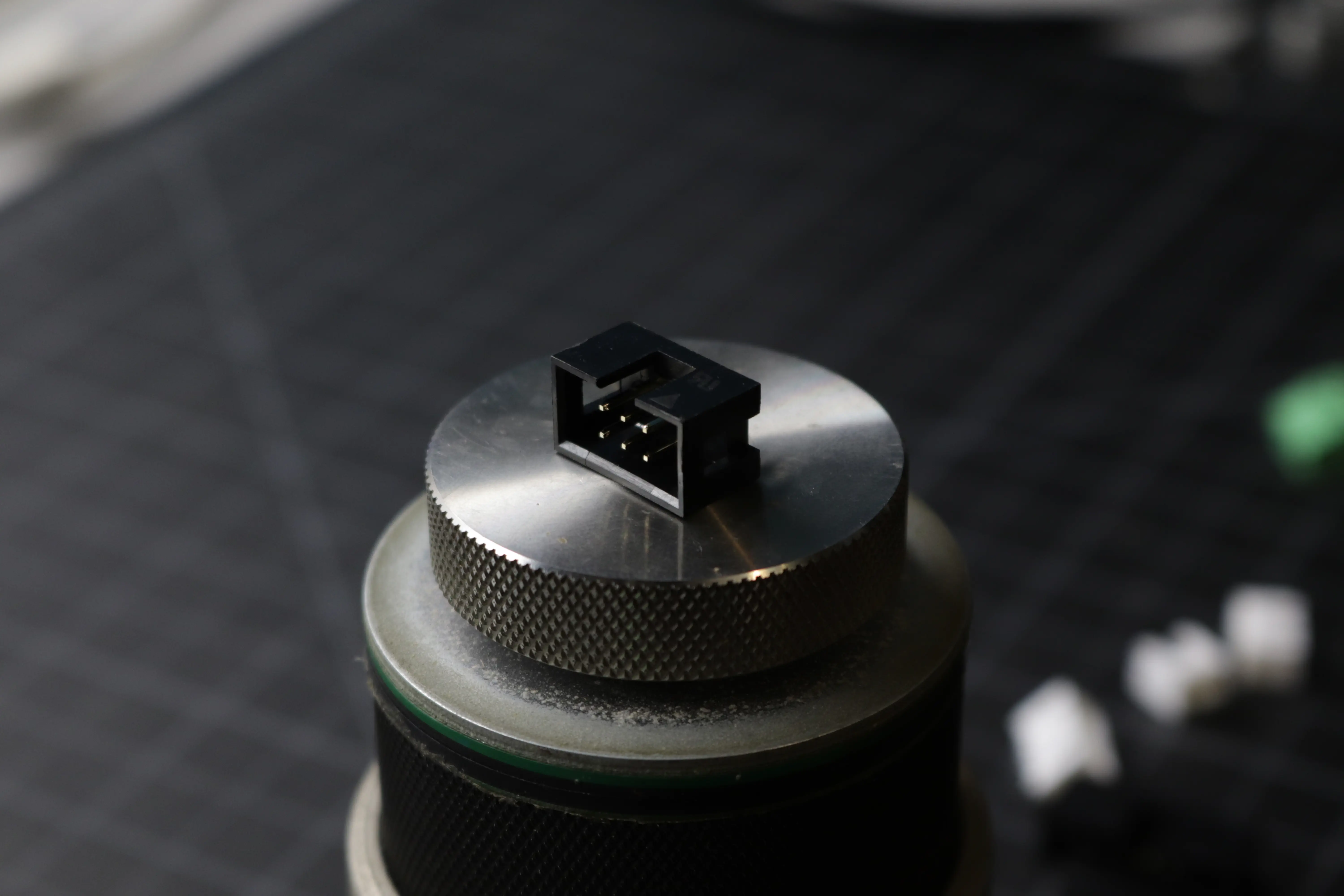
IDC Connectors
The IDC connectors are the larger, black connectors in your connector bag. There are only two sizes, a 2x3 for feeder communication, and three 2x6 for the auxillary ports. Be sure to solder them the correct orientation. The slot on the connector should match up with the silkscreen.
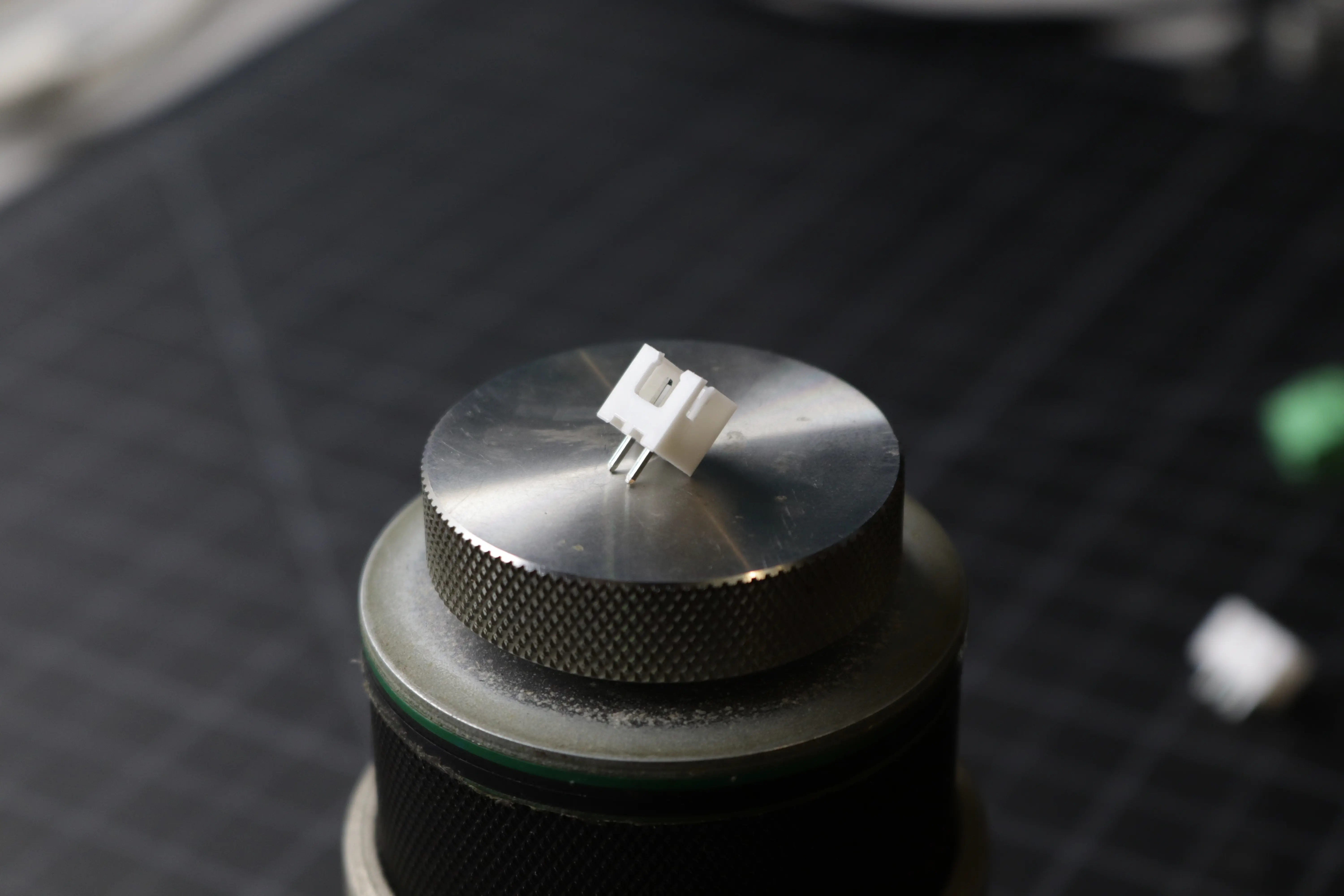
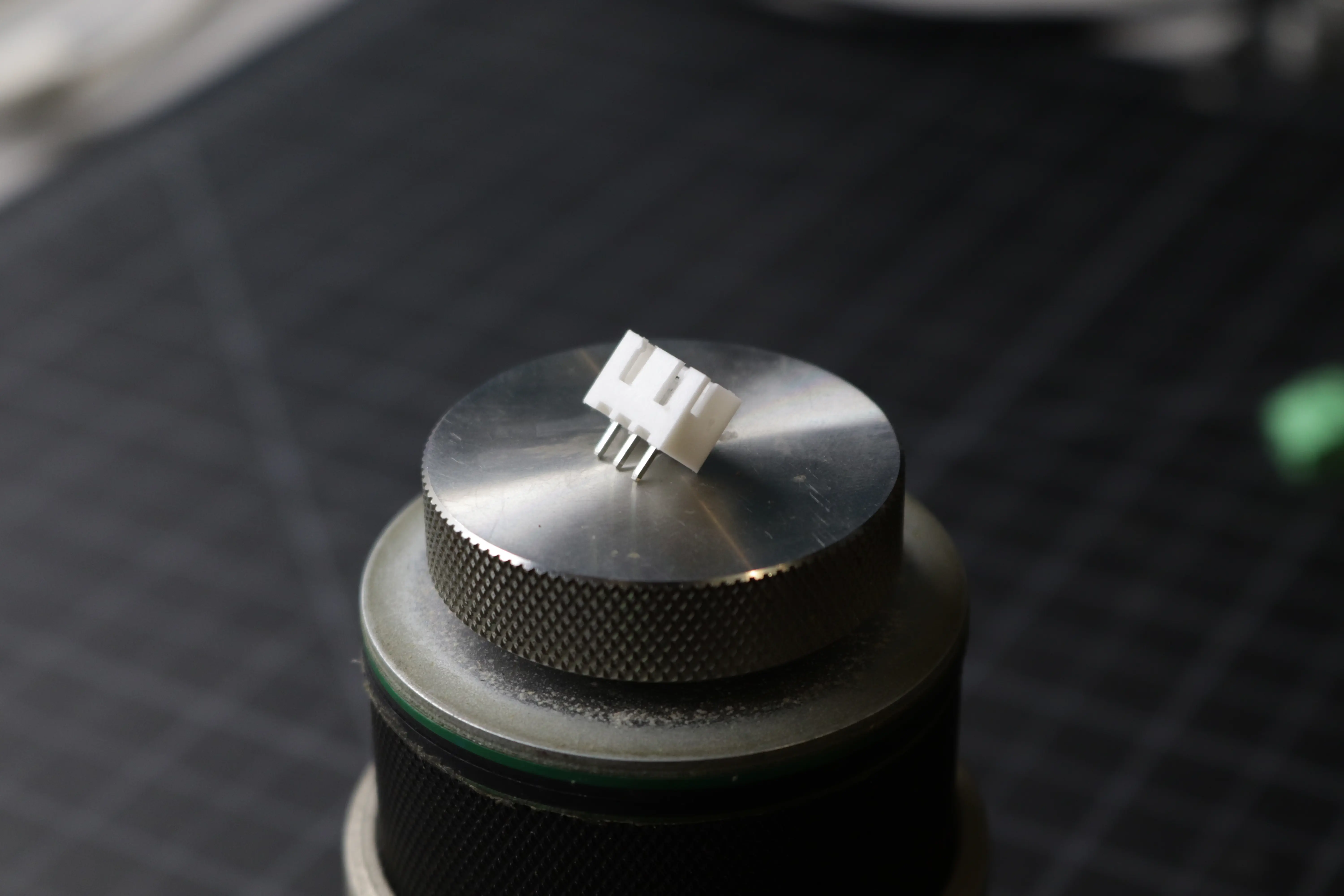
JST XH Connectors
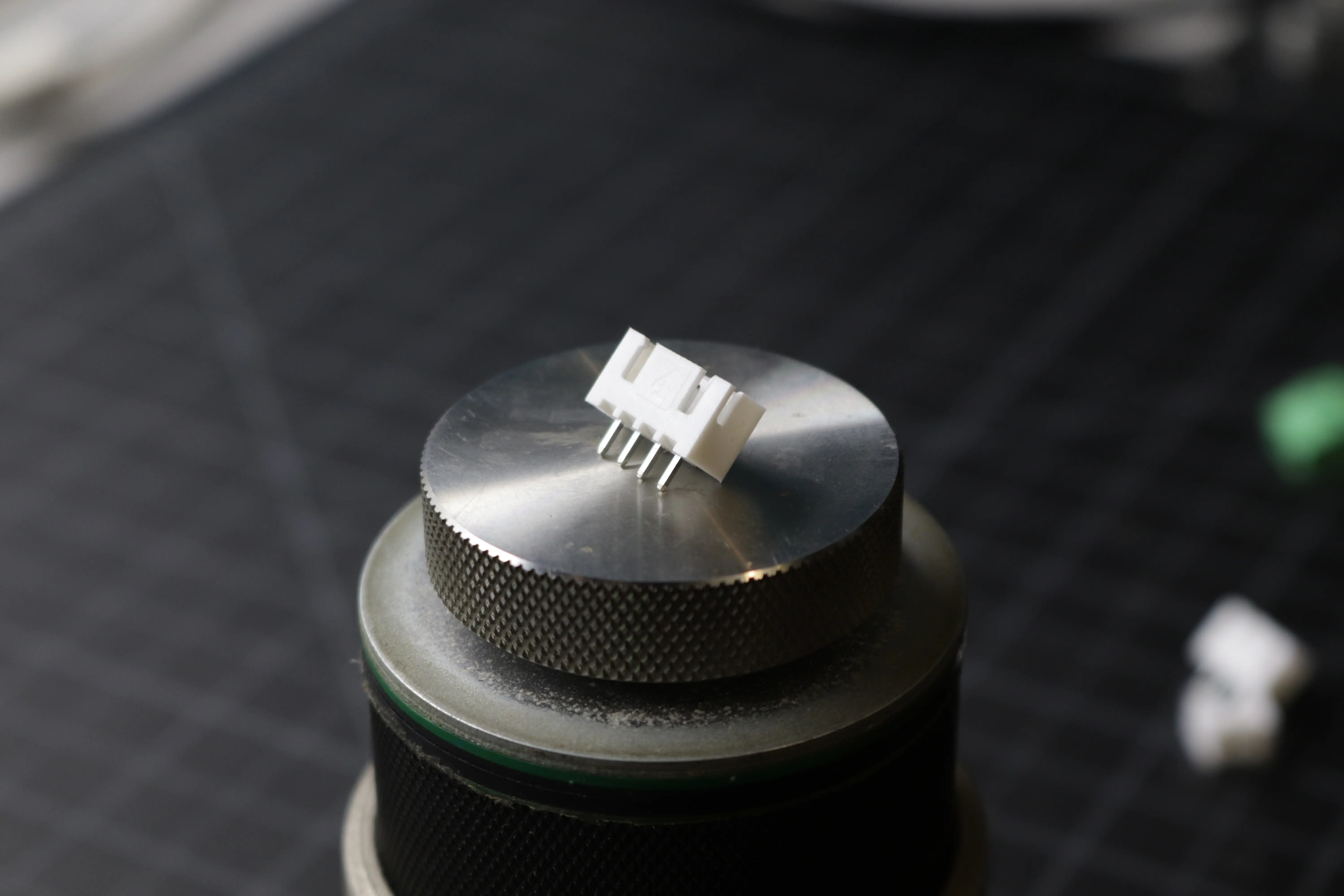
The bulk of the connectors on the board are JST XH connectors. These come in two, three, and four pin variations. The two pin connectors are for the mosfets, the three pin connectors are for the servos, limit switches, and ring lights, and the four pin connectors are for the stepper motors.
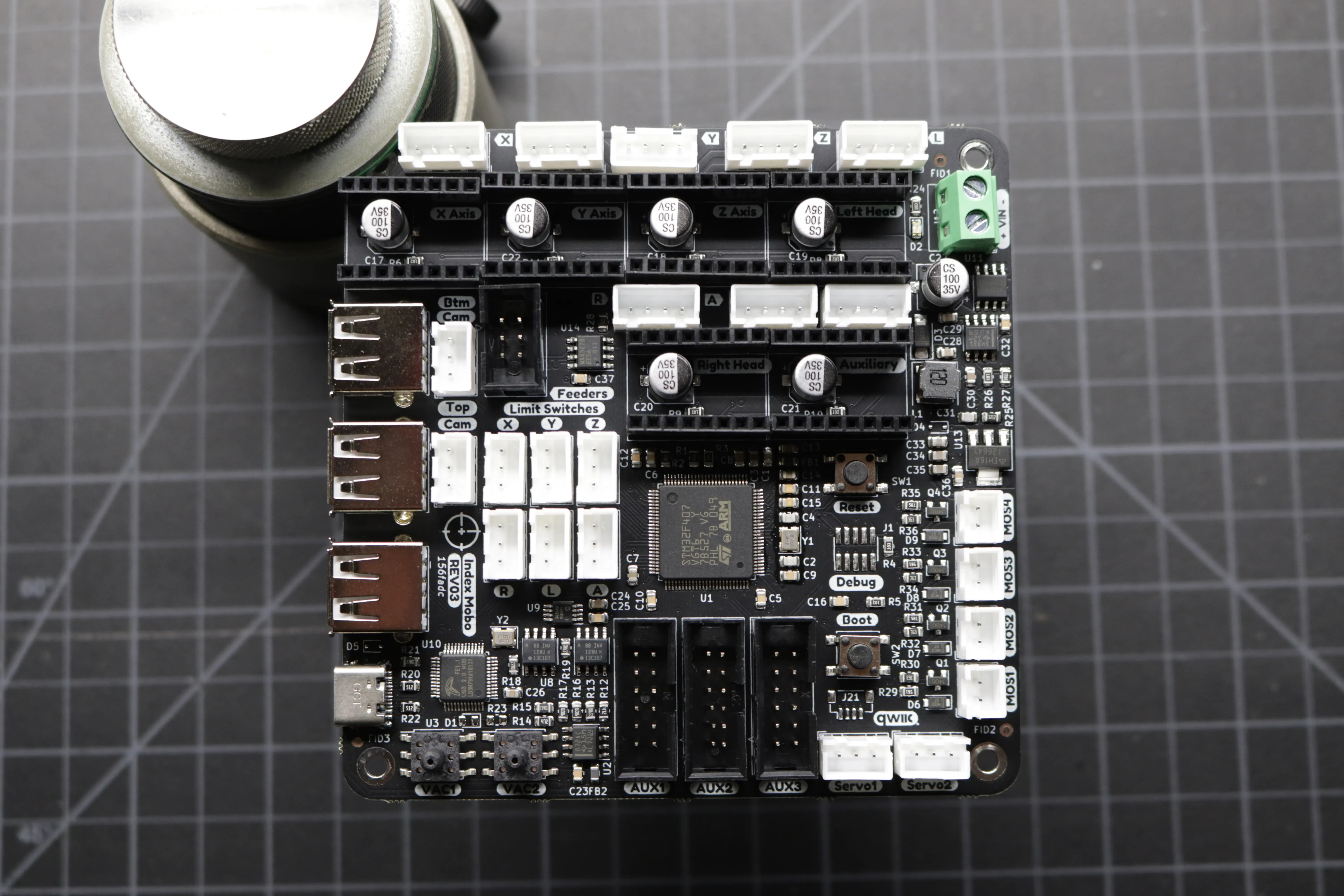
WARNING
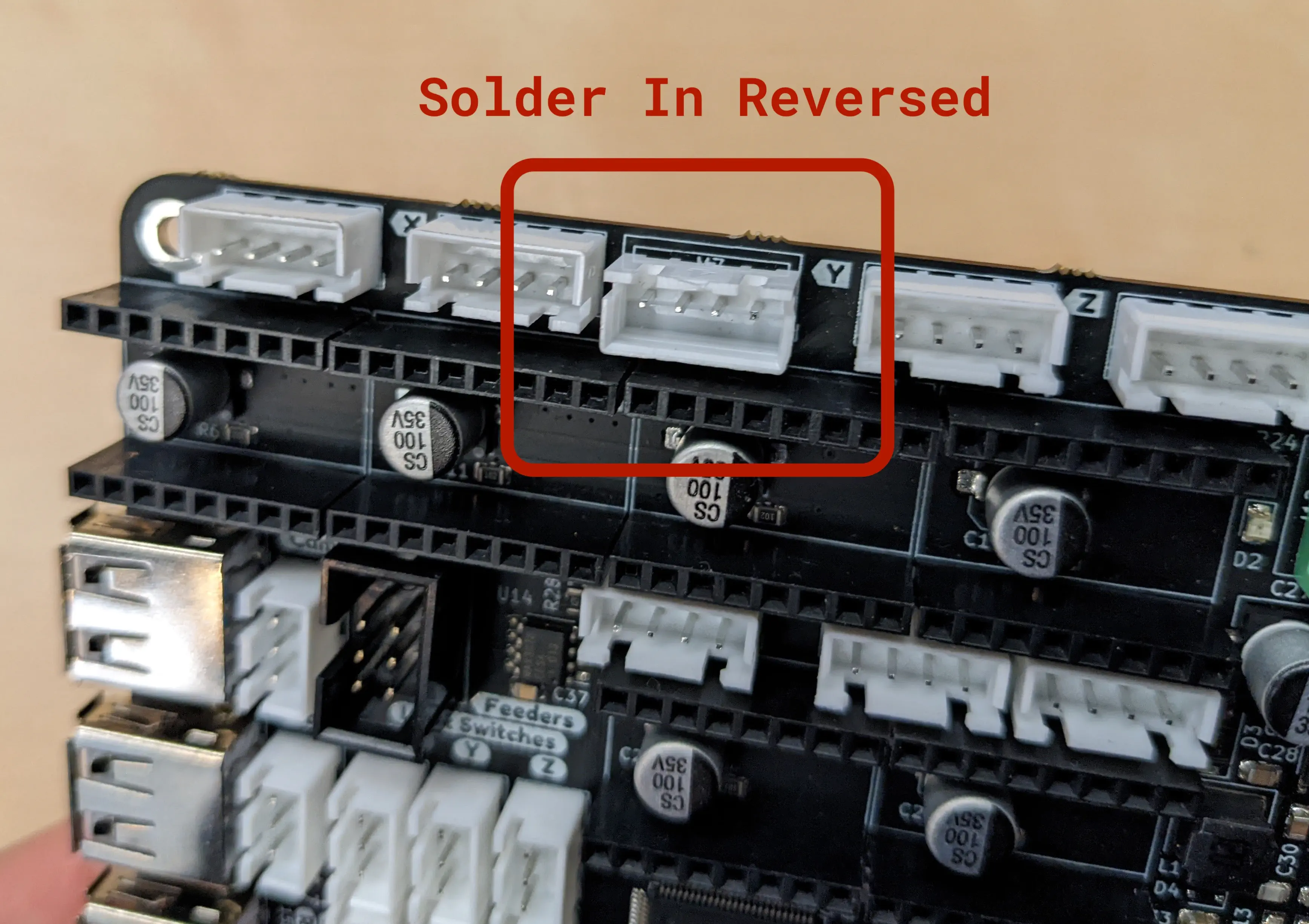
The 4-pin JST XH connector for the Y2 motor (the one right next to the Y silkscreen indicator) **needs to be rotated 180 degrees from what the silkscreen dictates**. This one should be soldered in reverse, opposite of the silkscreen indication. Refer to the image below for reference.
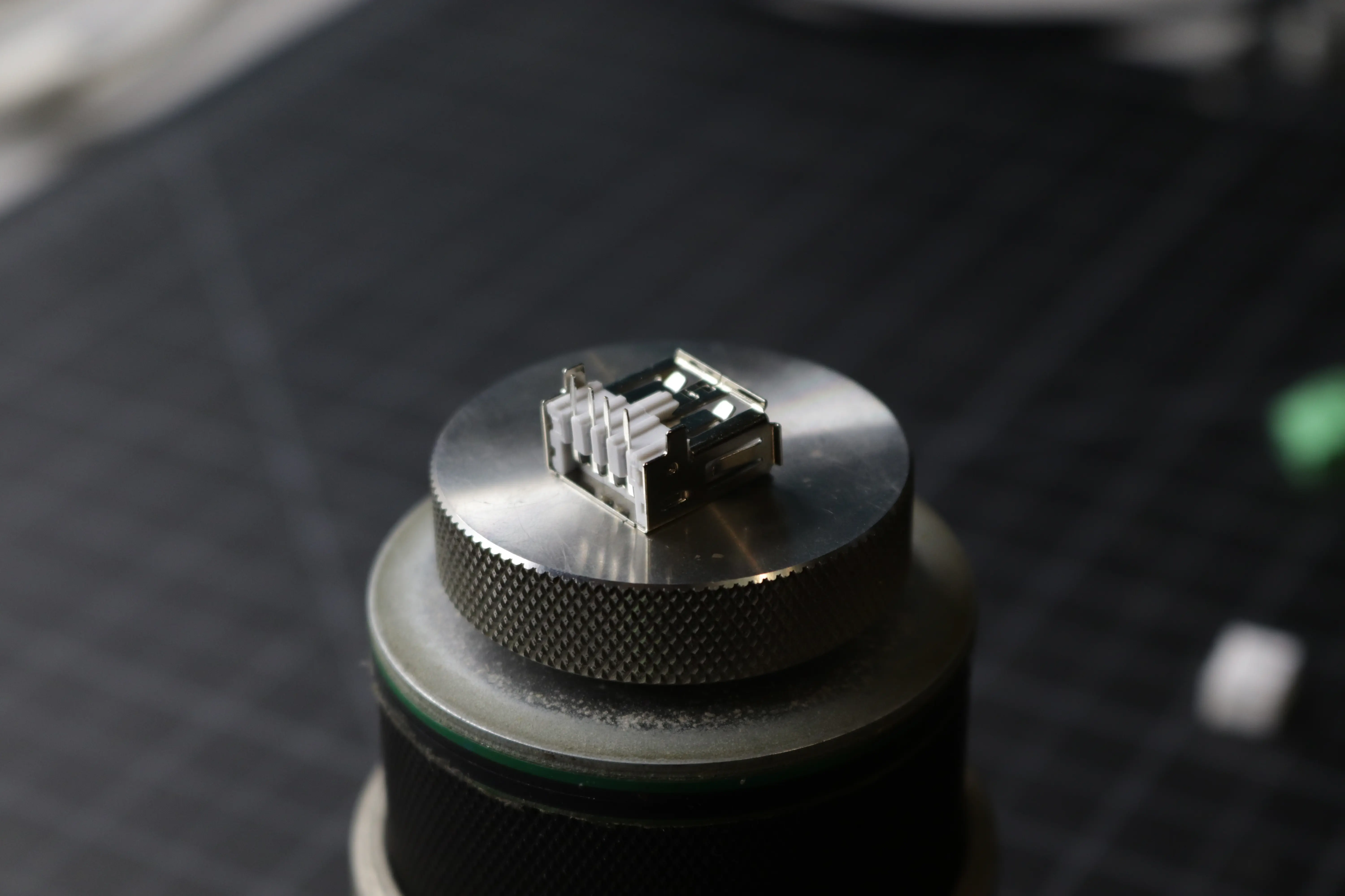
USB A Connectors
There are three USB A connectors that need to be soldered into the board as well. Two of these are for the webcams, and the third is for future functionality. We recommend soldering the large structural tabs in place first, then soldering the four data pins afterward.
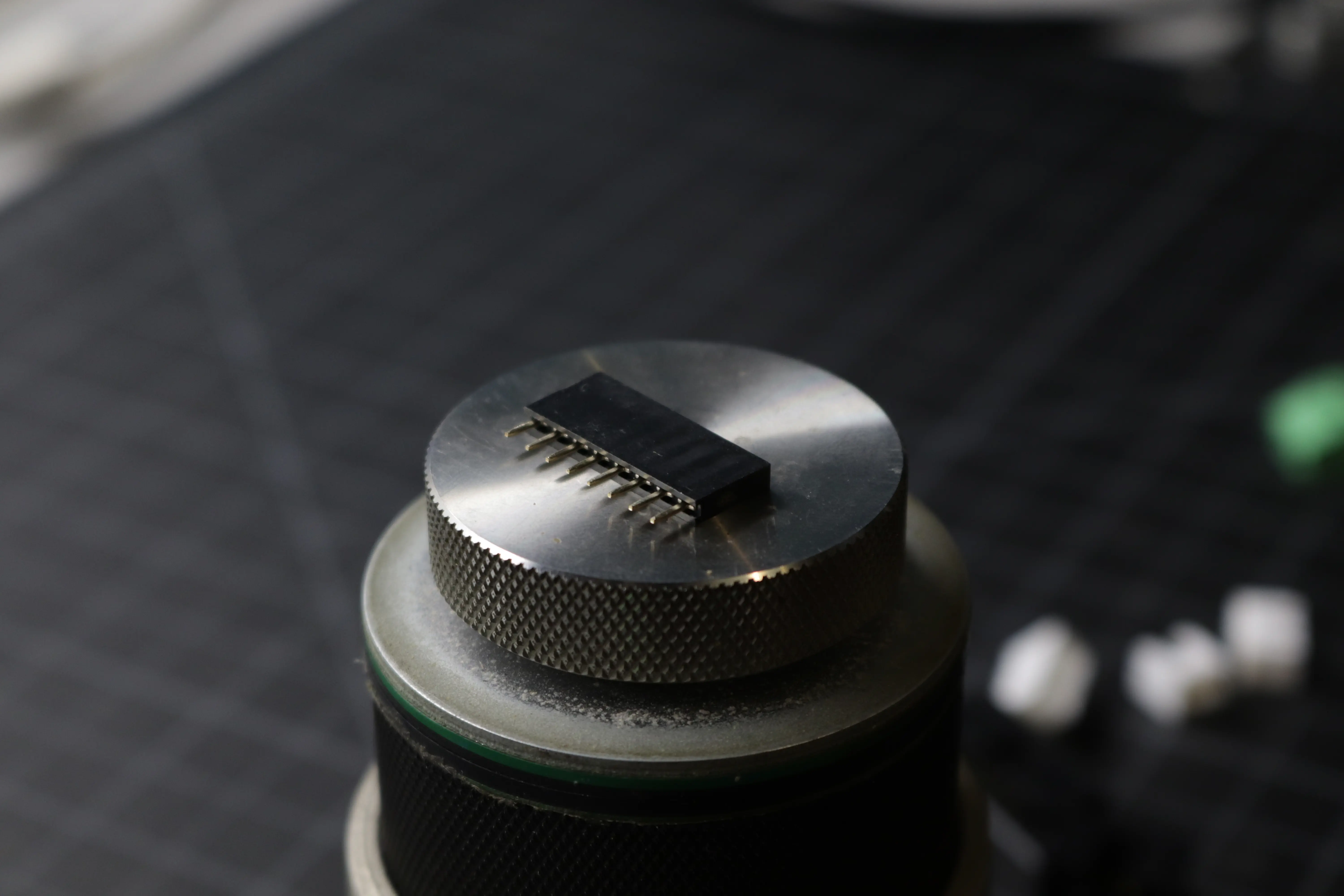
Stepper Motor Driver Headers
The last connectors that need to be soldered into the board are the 1x8 Dupont 0.1" headers for the stepper motor drivers. Two connectors need to be soldered for each driver. We recommend soldering a single pin in place first while getting the connector to stay flat, then do the rest of the pins after the orientation is solidified. Orientation does not matter for these connectors.
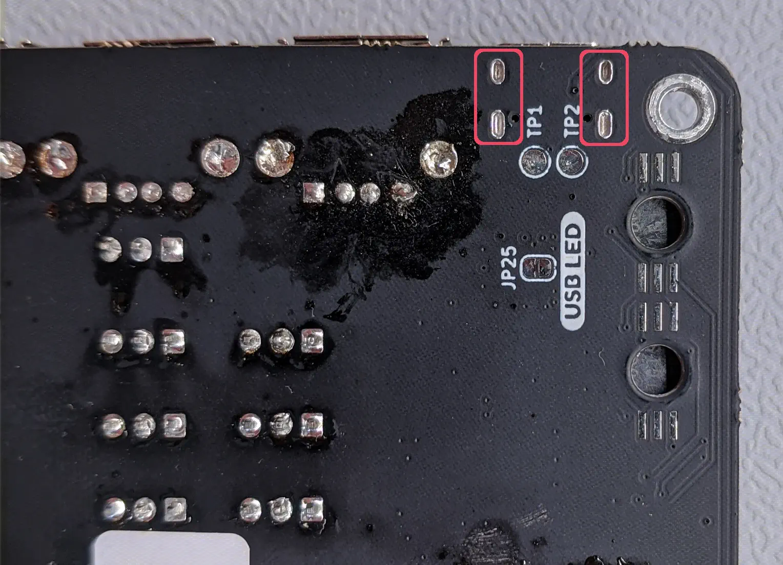
Double-check USB-C Feet
The LumenPnP motherboard will have the USB-C connector already soldered when you receive it. Double-check the soldering of the feet, as there was an early batch of motherboards that had issues with an in-house assembly error here. If you see an issue, take photos of it before attempting to repair the problem. That way, if you're unable to fix the issue, Opulo can still replace your motherboard for you. If you don't feel confident fixing an issue yourself or if you aren't sure if there's a problem with your motherboard, get in touch with us at support.opulo.io so that we can send you a replacement motherboard if necessary.
Next steps
Continue to mounting the motherboard.