MM/Pixel (Video Guide)
This next step calibrates the relationship between pixels and millimeters to make our cameras more accurate. But first, we're going to add some nozzle tips to our nozzles.
Mounting Nozzle Tips
-
Lubricate both of your brass nozzles using the included packet of SuperLube. We do this before shipping, but adding a bit extra ensures that mounting nozzle tips doesn't damage the rubber O-rings around the holder.
-
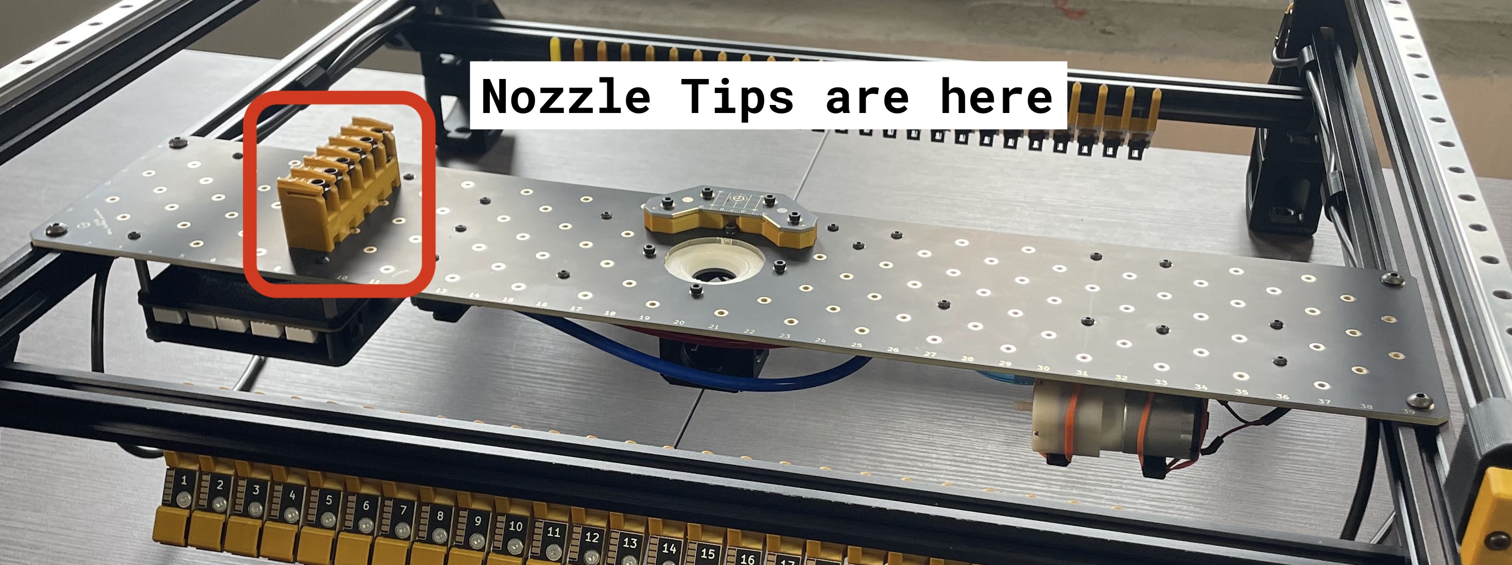
Identify your machine's nozzle tips. They're mounted in the rack on your staging plate.
-
Remove the nozzle tips labeled
N045andN24from the rack. -
In OpenPnP, navigate to
Machine Setup > Heads > ReferenceHead H1 > Nozzles > ReferenceNozzle N1and select theNozzle Tipstab, and check the checkbox in theLoaded?column for theN045row.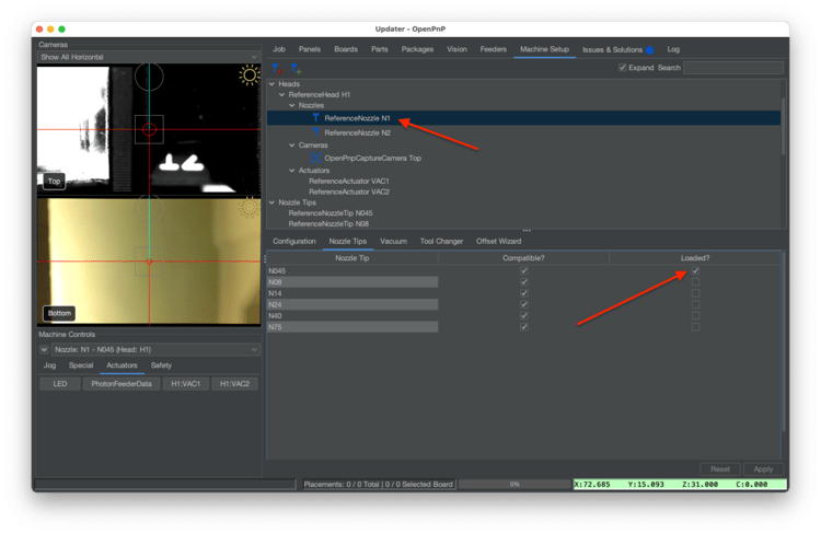
-
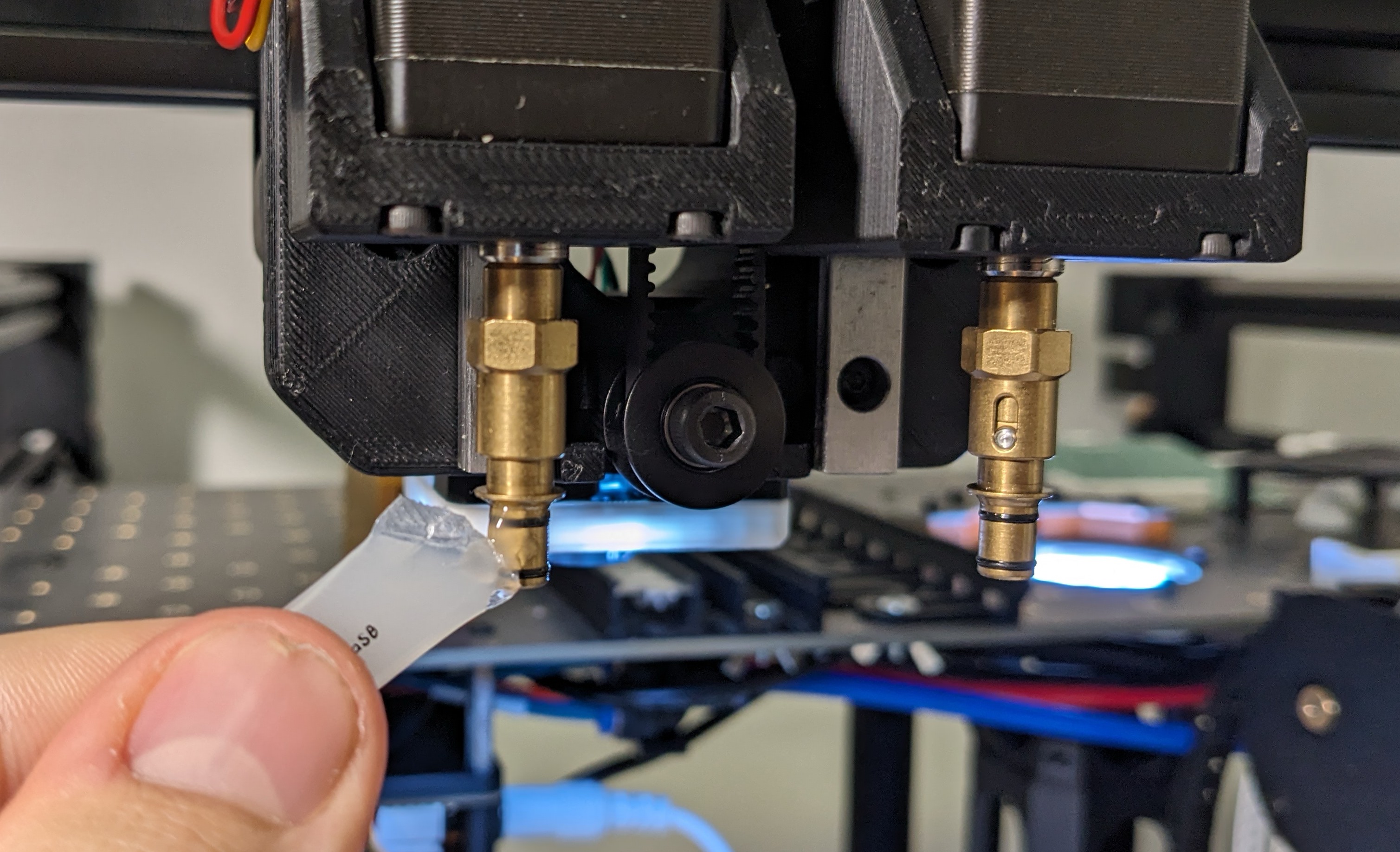
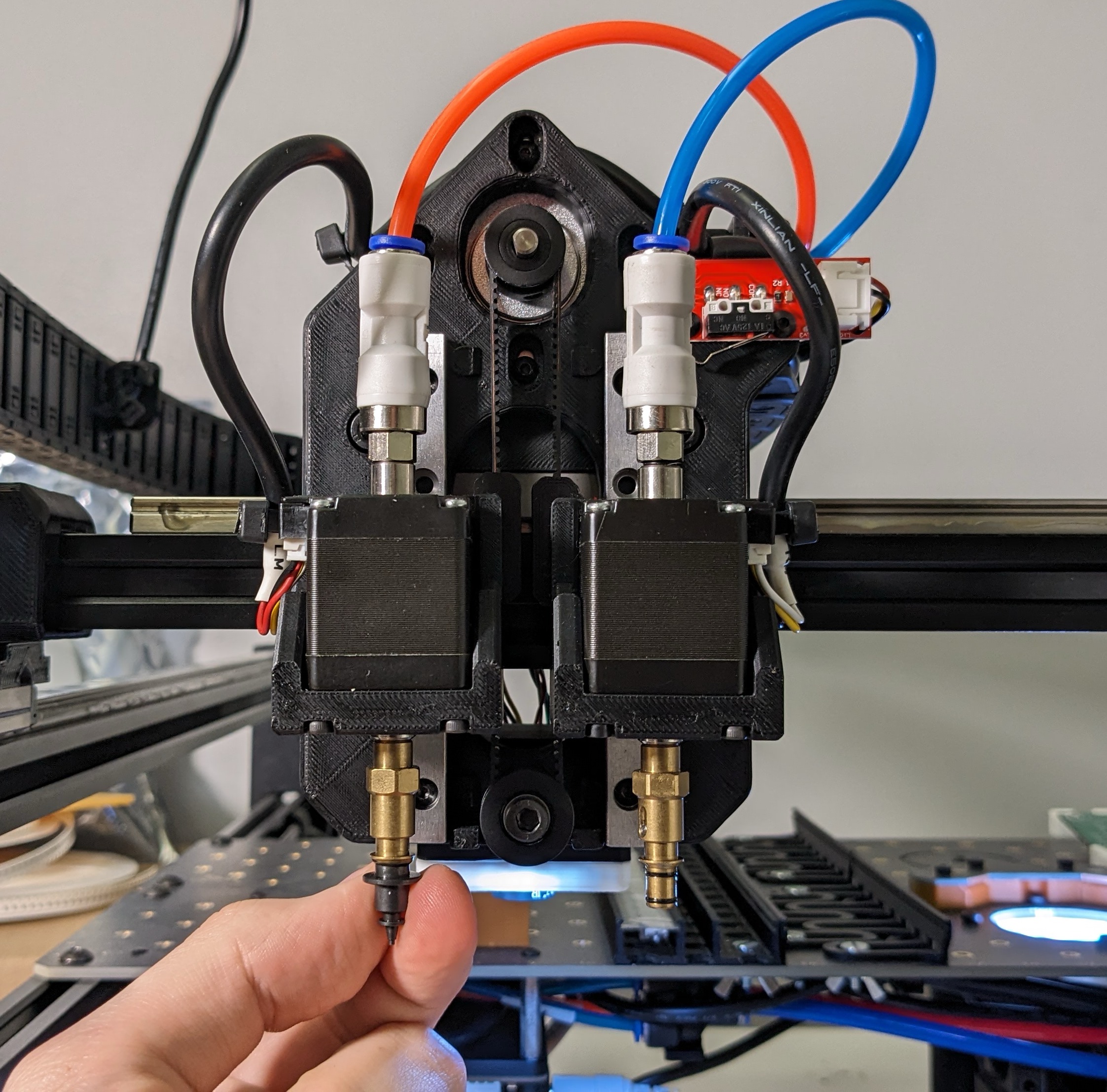
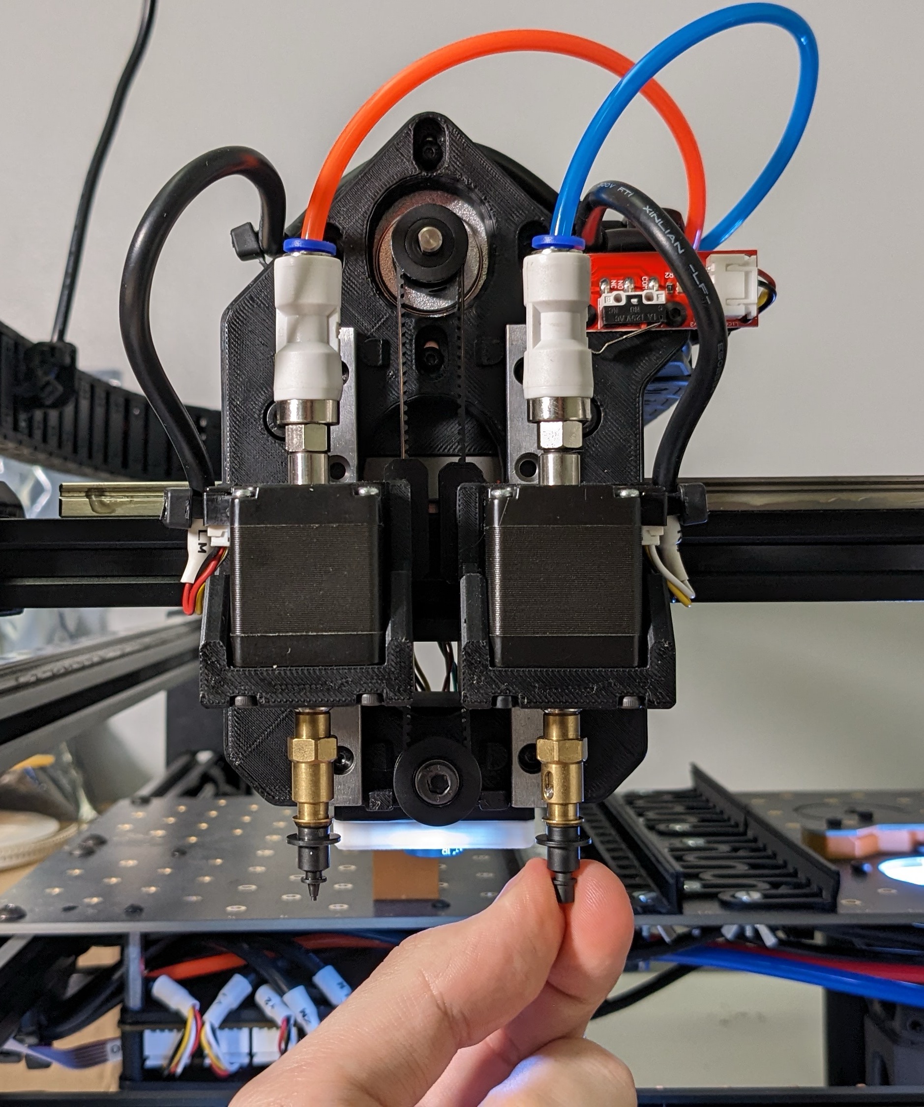
Your machine will jog the head to the front of the machine for easy tip loading. Slide the N045 nozzle tip (the one with the smaller opening) onto the left nozzle (using red tubing). Rotate the nozzle tip as you mount it to the brass holder to ensure the grease works its way into the tip and around the O-rings. It should slide on and off easily after working it in.
-
Now, navigate to the
ReferenceNozzle N2and select theNozzle Tipstab. This time, check the checkbox in theLoaded?column for theN24row.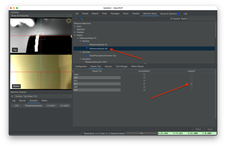
-
Slide the N24 nozzle tip (the one with the larger opening) onto the right nozzle (using blue tubing). Rotate the nozzle tip as you mount it to the brass holder to ensure the grease works its way into the tip and around the O-rings. It should slide on and off easily after working it in.
Tip
We mounted these two nozzle tips because these two sizes can pick the vast majority of parts without requiring a nozzle tip swap. Because of this, we highly recommend leaving these two tips mounted by default, and only swapping a tip if these two are unable to pick a part you need (typically very heavy parts).
Top Camera Calibration
-
Navigate to
Machine Setup > Heads > ReferenceHead H1.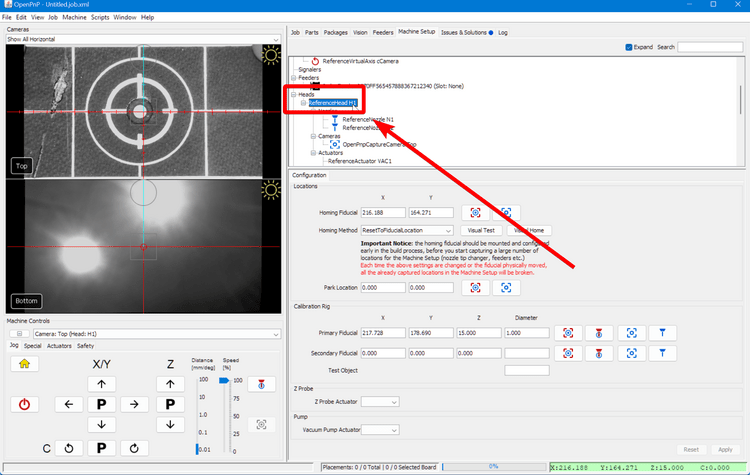
-
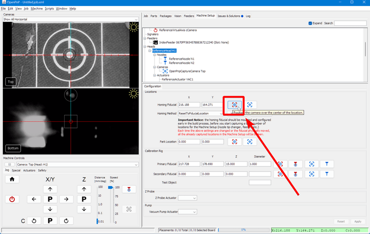
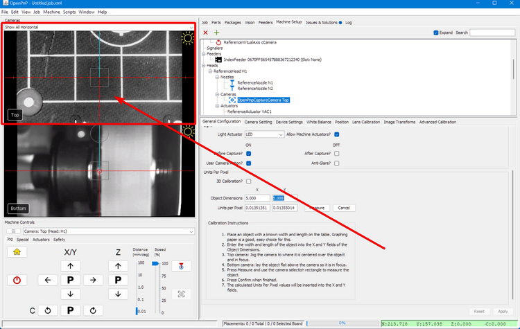
Click on the "Position Camera over location" icon button show below. This will move the top camera to where your datum board is mounted.
-
Click on
Heads > ReferenceHeadH1 > Cameras > OpenPnPCaptureCamera Top.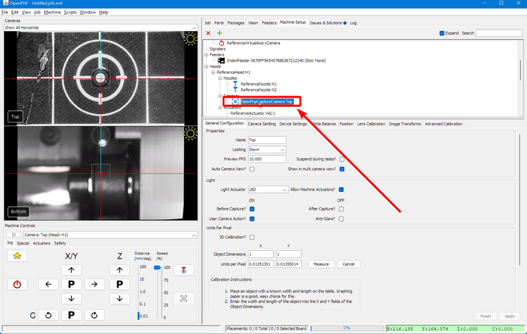
-
Go to the
General Configurationtab.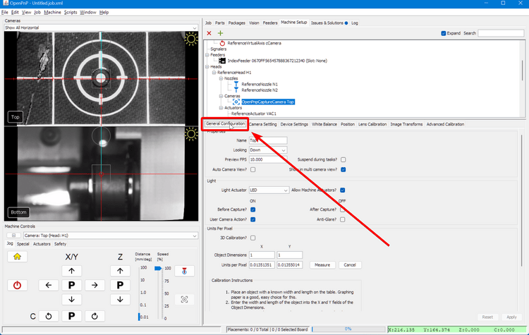
-
Scroll down to
Units Per Pixel.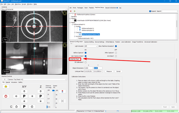
-
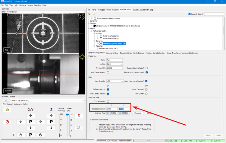
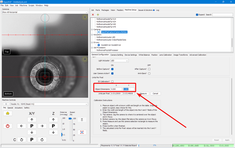
Set the X and Y Object Dimensions to
5.
-
Jog the machine so that one of the golden guideline squares on the datum board are visible in the top camera's view. The whole square must be visible. Zoom out of the camera feed with the scroll wheel if necessary.
-
Then click the
Measurebutton.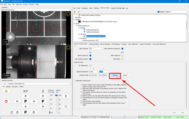
-
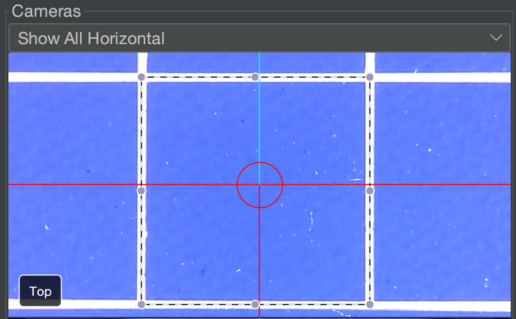
Click and drag in the camera view to create a box. Drag the box so that it lines up with the lines on the datum board; they are exactly 5mm x 5mm. Make sure that you are aligning the bounding box with the center of the lines as shown in the image below.
Squareness
Don't worry if the square fo the box doesn't perfectly align with the camera image. Any slight skew will be adjusted for duing jobs with fiducial calibration.
-
Once you have it perfectly outlined, click the
Measurebutton again. The new calibration numbers will populate the Units per Pixel fields. They should be relatively close to the default values.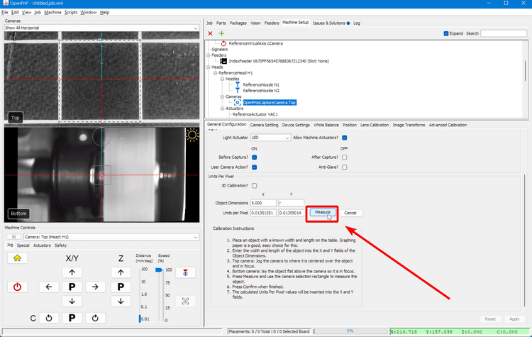
-
Click
Applyto save the changes.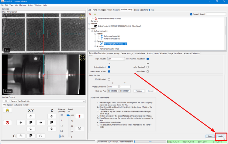
-
To confirm, drag the reticle on the top camera view to move the machine. The camera center should move exactly where you tell it to. If it's inaccurate, try doing the calibration again or tweaking the values in the fields.
Bottom Camera Calibration
-
Rehome your machine using the home button.
-
Navigate to
Machine Setup > Cameras > OpenPnPCaptureCamera Bottom, then select thePositiontab.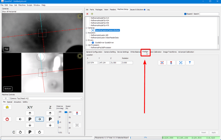
-
In the drop down under
Machine Controlson the left, selectNozzle: N2so that for any nozzle commands we run, OpenPnP knows to make them based on N2 and not N1.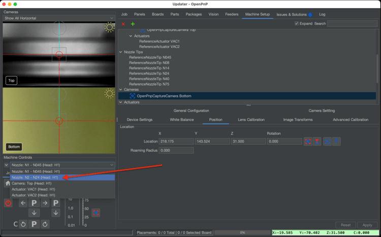
-
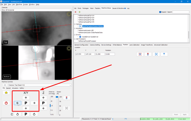
Click on the "Position Nozzle Over Location" button
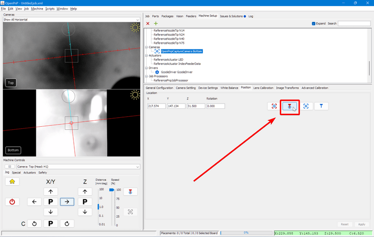
-
Use the jog controls to move the nozzle directly over the center of the bottom camera. Do not adjust the Z-axis.
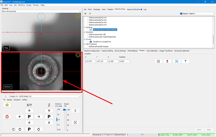
Adjusting Focus
Focus is adjusted before shipping, but if you'd like to fune tune your adjustment, you can twist the lens of the bottom camera. You'll need to loosen the set screw on the side to allow it to turn.
-
Go to the
General Configurationtab.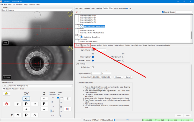
-
Scroll down to
Units Per Pixel.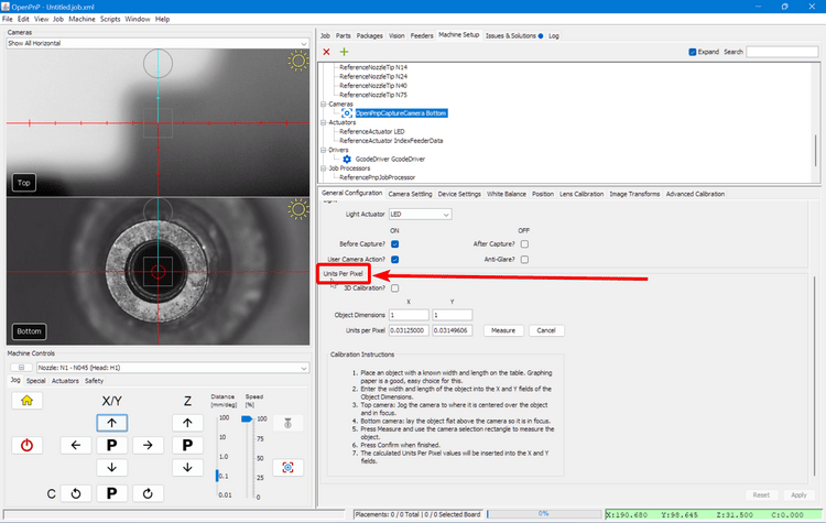
-
Set the X and Y Object Dimensions to
4.
-
Then click the
Measurebutton.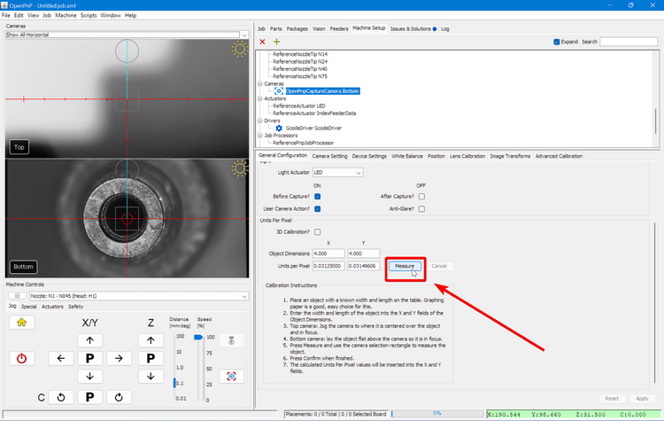
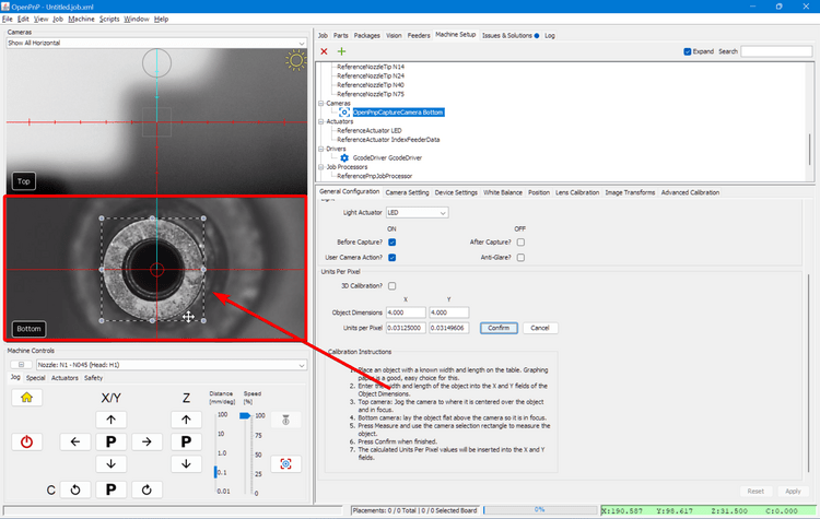
-
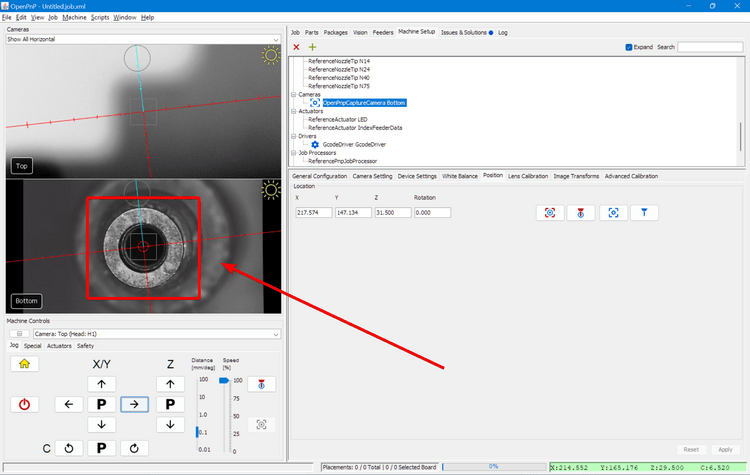
Click and drag in the bottom camera viewfinder to bring up a bounding box. Drag the bounding box around the nozzle tip so that it's perfectly tangent to the edges as shown in the image.
-
Once you have it perfectly outlined, click
Measureagain. New numbers should populate the Units per Pixel fields. They should be relatively close to the default values.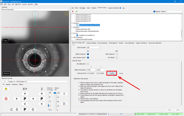
-
Then click
Applyto save the changes.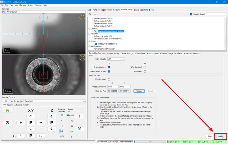
-
To confirm, drag the reticle on the bottom camera view to move the machine. The nozzle tip should move exactly where you tell it to. If it's inaccurate, try doing the calibration again or tweaking the values in the fields.
Next Steps
Next is Nozzle Offset Calibration.