Vacuum Part Detection
![]()
When picking up parts with the LumenPnP, it’s important to verify that a part has been successfully picked. While the bottom camera also confirms this visually, using the LumenPnP's vacuum sensors provides a faster way to detect a successful pick, preventing it from having to bring the component to the bottom camera first to detect the part. Because the bottom camera does checks the part, even if slightly slower, you can freely disable the vacuum part detection with confidence that you'll still be able to place your parts.
How Vacuum Part Detection Works
When a part is picked up, it seals the nozzle opening, causing an increase in vacuum pressure within the pneumatic line. This change in pressure is measured by the vacuum sensors, and OpenPnP uses this data to determine whether a part has been successfully picked. With the nozzle tip covered, if the vacuum sensor value falls within the Vacuum Range low and high values, OpenPnP considers the part "picked".
Each nozzle has a different vacuum reading due to variations in nozzle tip size. The exact numbers aren’t critical as long as you understand how to set the high and low values correctly and adjust them accordingly.
Disabling Vacuum Detection is an Option
Vacuum Part detection is not required to use the LumenPnP because the bottom camera checks for a part before placing anyway. If you'd like to disable this feature, it's just a matter of setting "Measurement Method" to "None" on the relevant nozzle tip. Don't forget to Apply your settings and save your configuration before moving on. Machine Setup > Nozzle Tips > Reference Nozzle Tip N## > Part detection tab > Measurement Method > None
Setting Up Vacuum Part Detection for Nozzle: N1
-
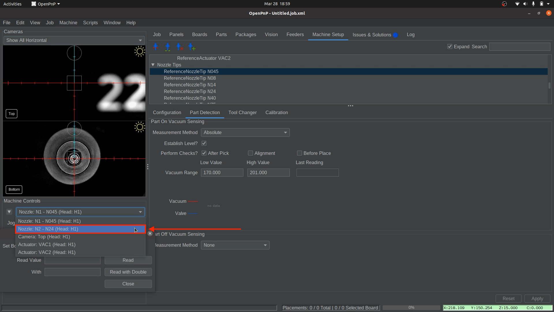
Select the correct nozzle to control.
- In the bottom left of OpenPnP, select
Nozzle: N1 - N045 (Head:H1)from the machine controls dropdown.
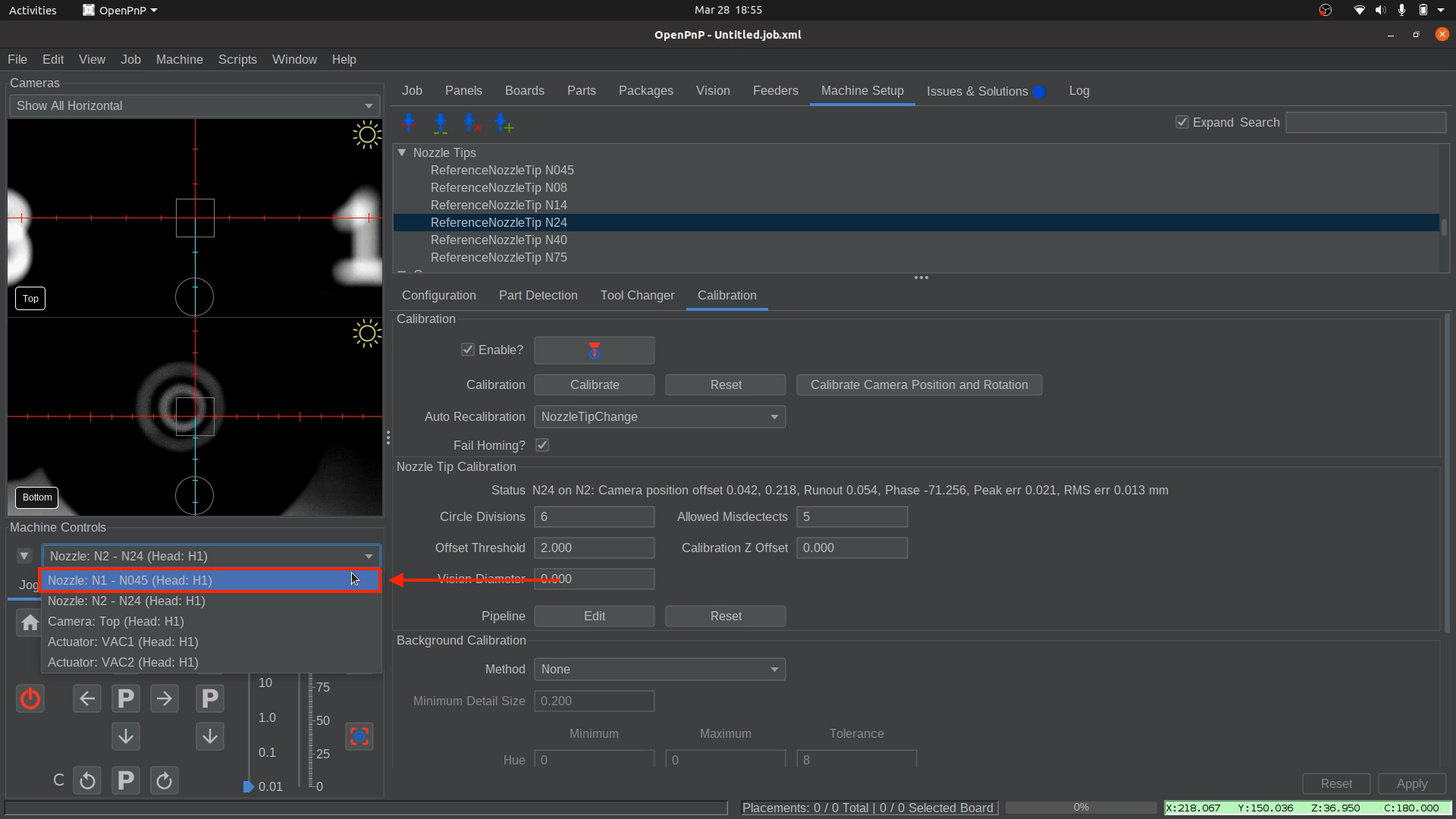
- In the bottom left of OpenPnP, select
-
Confirm the correct nozzle tip is installed.
- Ensure that the
N045nozzle tip is securely attached to Nozzle: N1 (left toolhead).
- Ensure that the
-
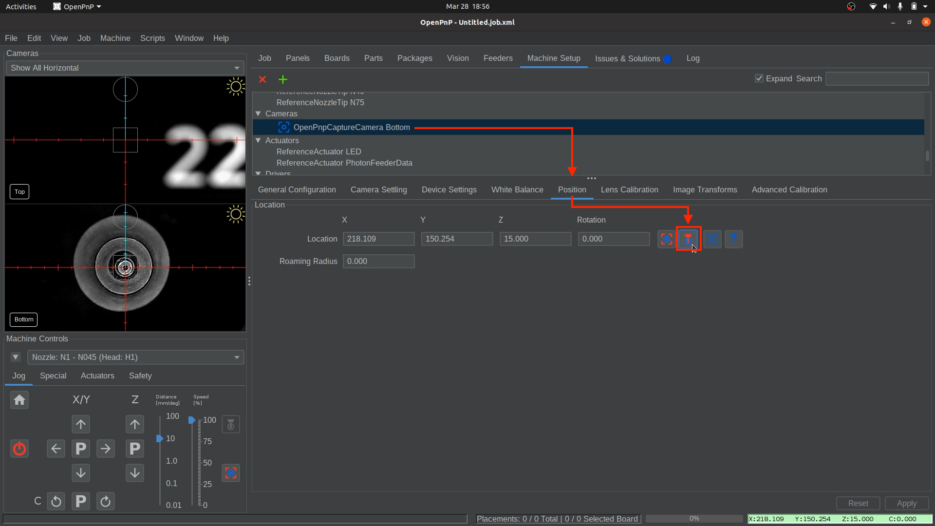
Position Nozzle: N1 for Accurate Readings.
- Navigate to
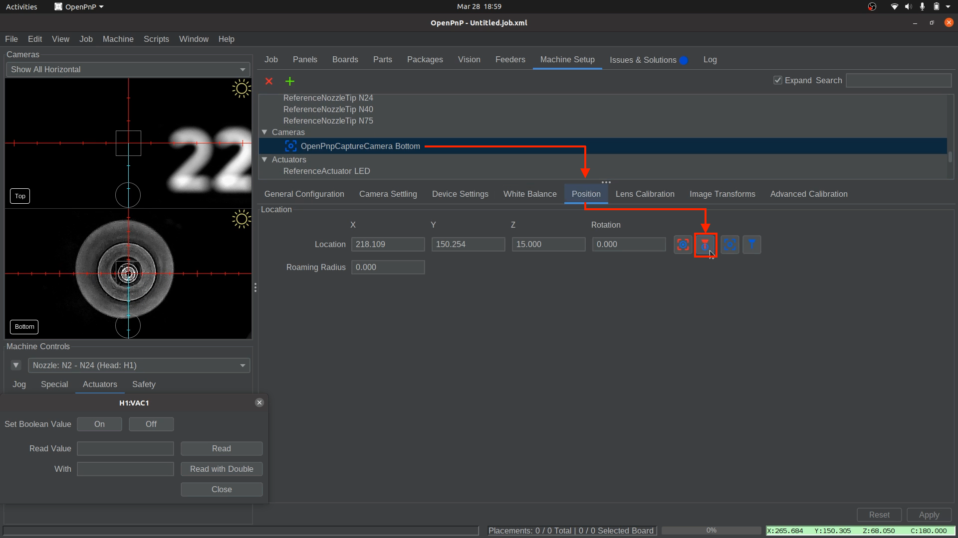
Machine Setup > Cameras > OpenPnPCaptureCamera Bottom > Position tab - Click the
Position the tool over the center of the locationbutton. - This brings the
nozzle: N1to the same Z height as the datum board, ensuring more consistent readings for the following steps.
- Navigate to
-
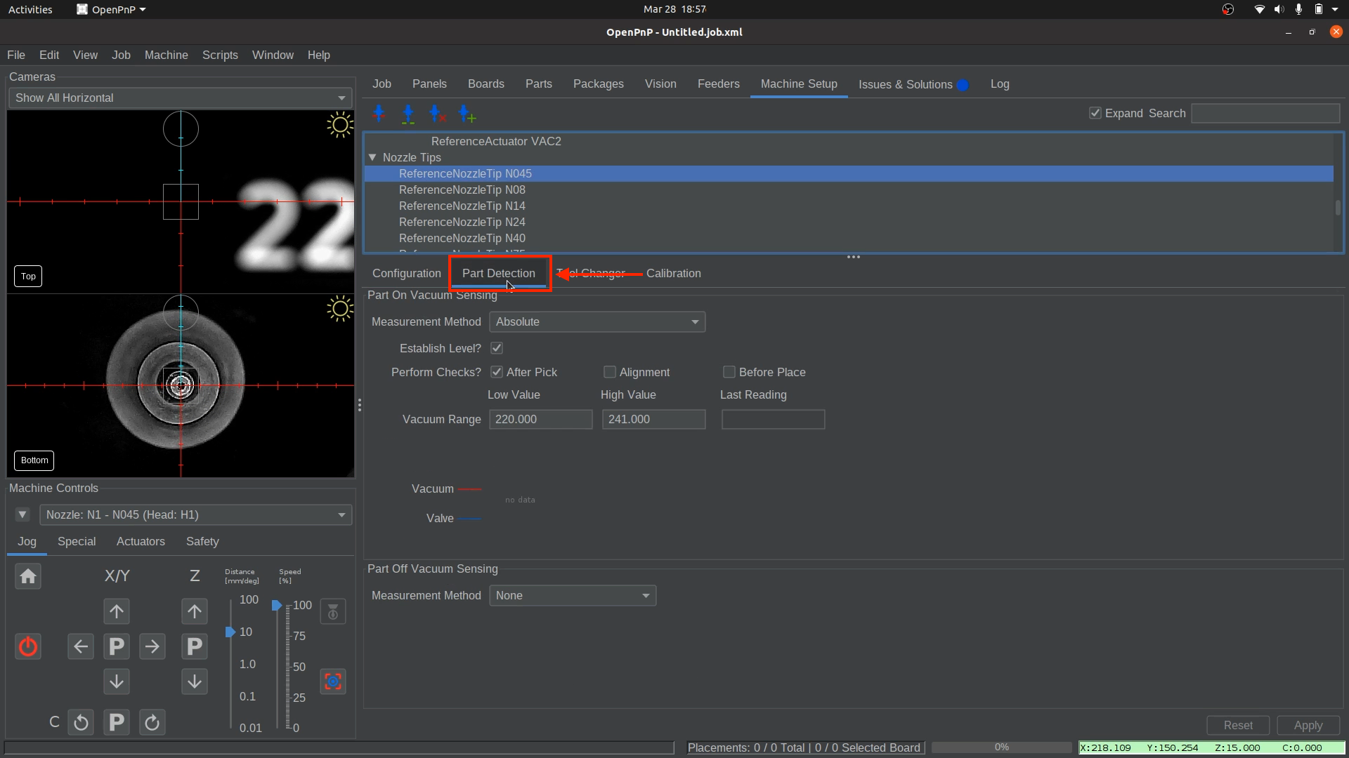
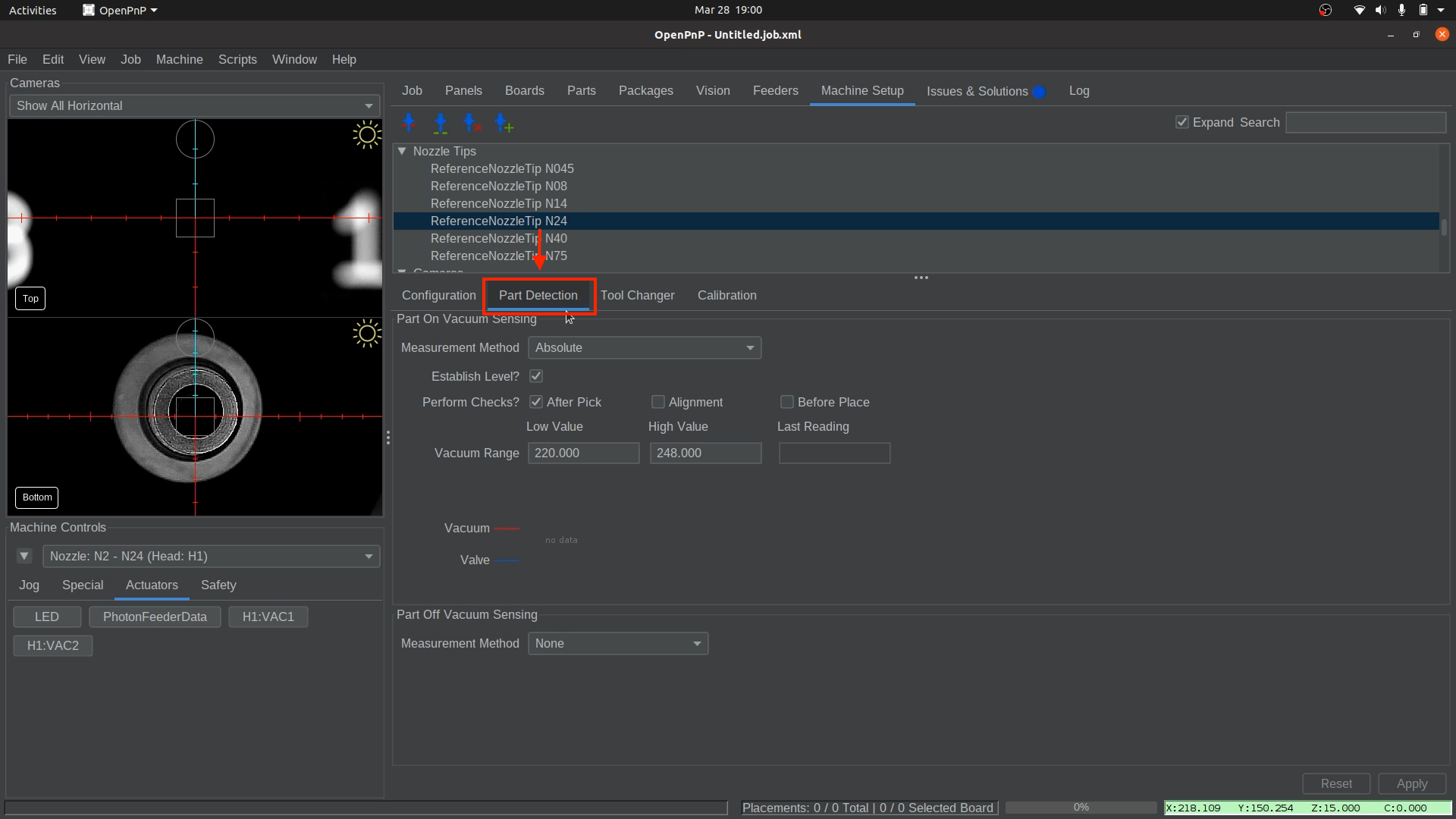
Open the Part Detection Settings.
- Navigate to
Machine Setup > Nozzle Tips > ReferenceNozzleTip N045 > Part Detection.
- Navigate to
-
Measure the Vacuum Pressure While Open.
- In
Machine Controls, navigate to theActuatorstab. - Select
H1:VAC1to open the vacuum pressure window. - Click
Onto activate the pump and valve.
- Click
Read. A value will appear in theRead Value box. This represents the vacuum pressure when the Nozzle: N1 is uncovered. - Take note of this number. We will need it later.
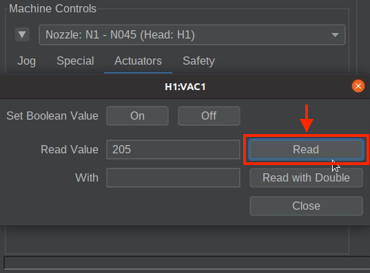
- In
-
Measure the Vacuum Pressure While Covered.
- Take one of the components from the strip of components included with your LumenPnP kit, or a component from your BOM that is an appropriate size for this nozzle, and hold it up to the nozzle tip. The vacuum pressure should be able to pick up and hold the part on its own.
- Click
Readagain. This represents the vacuum pressure when a part is picked, or "covered".
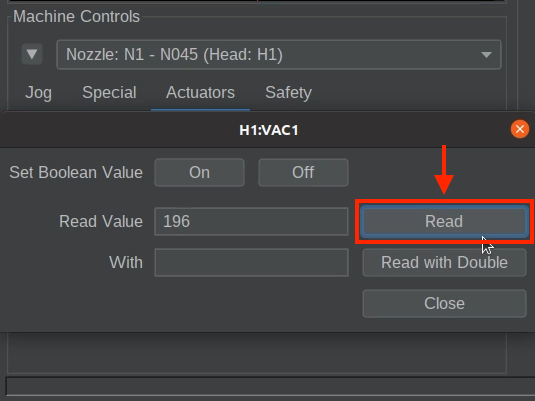
- Take note of the new value. We will also need it later.
- Click
Offto deactivate the pump and valve. - Close the
H1:VAC1vacuum pressure window.
-
Calculate the Detection Threshold.
- Find the midpoint between the uncovered and covered values. For example:
- Uncovered: 220
- Covered: 200
- Midpoint: 210 → Enter this as the
High Value.

- Enter the calculated midpoint value into the Vacuum Range
High Valuefield for the N045 nozzle tip. - Ensure the
Low Valueis at least 10-20 units lower than the "Midpoint" reading. The default low value is 220, but if your readings are close to this number (like the example above), you may need to lower it further to avoid false detections. If your Midpoint value is 210, setting theLow Valueto 190 (or lower) is a good starting point.

Caution
The difference between uncovered and covered readings may be small, but even a single-digit change can indicate a successful pick. Nozzle sizes affect these readings, so expect variations between nozzles.
- Find the midpoint between the uncovered and covered values. For example:
-
Apply and Save
- Click
Applyin the lower right corner to save your changes to the N045 nozzle tip.
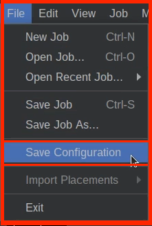
- Save your OpenPnP configuration now.
File > Save Configuration.
- Click
Setting Up Vacuum Part Detection for Nozzle: N2
-
Select the correct nozzle to control.
- In the bottom left of OpenPnP, select
Nozzle: N2 - N24 (Head:H1)from the machine controls dropdown.
- In the bottom left of OpenPnP, select
-
Confirm the correct nozzle tip is installed.
- Ensure that the
N24nozzle tip is securely attached to Nozzle: N2(right toolhead).
- Ensure that the
-
Position Nozzle: N2 for Accurate Readings.
- Navigate to
Machine Setup > Cameras > OpenPnPCaptureCamera Bottom > Position tab - Click the
Position the tool over the center of the locationbutton.
- This brings the
Nozzle: N2to the same Z height as the datum board, ensuring more consistent readings for the following steps.
- Navigate to
-
Open the Part Detection tab.
- Navigate to
Machine Setup > Nozzle Tips > ReferenceNozzleTip N24 > Part Detection.
- Navigate to
-
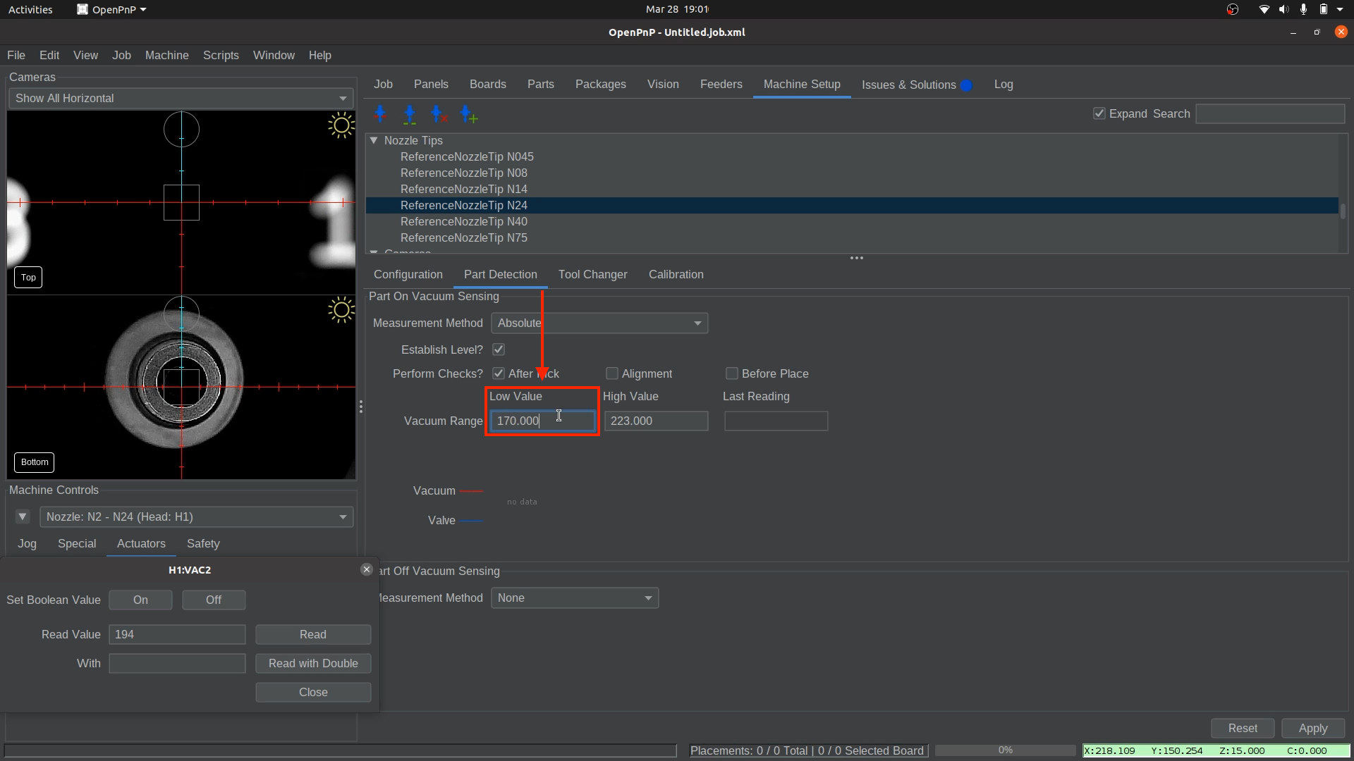
Measure the Vacuum Pressure.
- In
Machine Controls, navigate to theActuatorstab. - Select
H1:VAC2to open the vacuum pressure window. - Click
Onto activate the pump and valve.
- Click
Read. A value will appear in theRead Value box. This represents the vacuum pressure when Nozzle: N2 is uncovered. - Take note of this number. We will need it later.
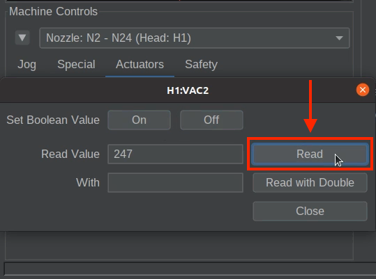
- In
-
Measure the Vacuum Pressure with a Sealed Nozzle.
- Take a component from your BOM that is an appropriate size for this nozzle and hold it up to the nozzle tip. The vacuum pressure should be able to pick up and hold the part on its own. If you do not have a component large enough for this nozzle tip, you may use your fingertip as a fallback. However, using an actual component will provide the most accurate results.
- Click
Readagain. This represents the vacuum pressure when a part is picked, or "covered".
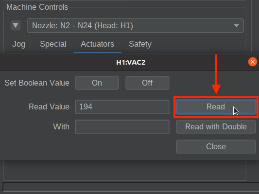
- Take note of the new value. We will also need it later.
- Click
Offto deactivate the pump and valve. - Close the
H1:VAC2vacuum pressure window.
-
Calculate the Detection Threshold.
- Find the midpoint between the uncovered and covered values. For example:
- Uncovered: 230
- Covered: 200
- Midpoint: 215 → Enter this as the
High Value.
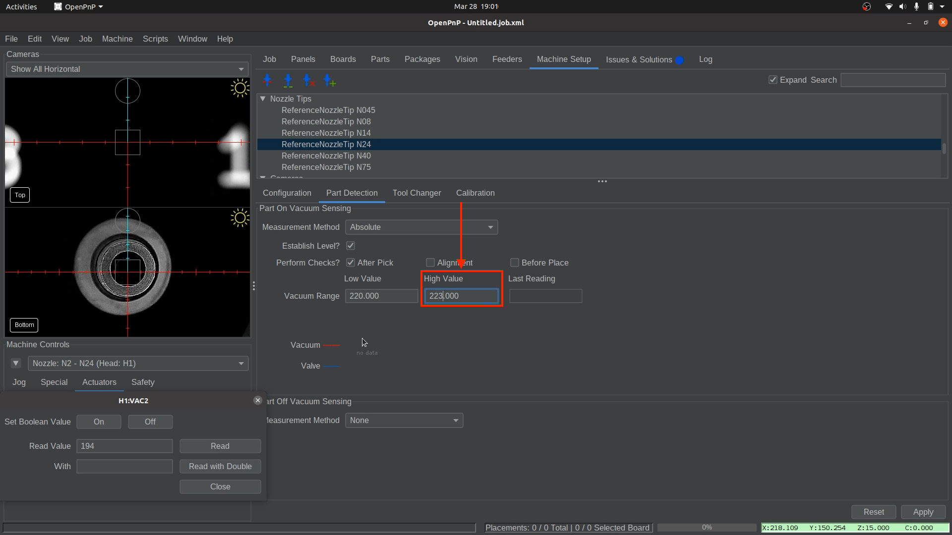
- Enter the calculated midpoint value into the Vacuum Range
High Valuefield for the N24 nozzle tip. - Ensure the
Low Valueis at least 10-20 units lower than the "Midpoint" reading. The default low value is 220, but if your readings are close to this number(like the example above), you may need to lower it further to avoid false detections. If your Midpoint value is 215, setting theLow Valueto 195 (or lower) is a good starting point.
Don't forget
The difference between uncovered and covered readings may be small, but even a single-digit change can indicate a successful pick. Nozzle sizes affect these readings, so expect variations between nozzles.
- Find the midpoint between the uncovered and covered values. For example:
-
Apply and Save
- Click
Applyin the lower right corner to save your changes to the N24 nozzle tip.
- Save your OpenPnP configuration now.
File > Save Configuration.
- Click
For LumenPnP v2 Machines Only
Skip this section if you are not setting up a LumenPnP V2.
v2 Interposers
If you have a v2 machine, please check if you have interposer boards installed.
-
Select your GcodeDriver, then under the Gcode tab, select the
H1 VAC1actuator, and select theACTUATOR_READ_COMMANDsetting. -
Make sure the following Gcode is present in the field:
M3426 G2 C1 I1 A110Sensor Address
In the above code snippet, the line
M3426 G4 C1 I1 A110usesA110to specify which sensor to read from. Due to the way the sensors are programmed by their manufacturer, the address of the sensor can vary. IfA110doesn't work for you, try testing each binary value from0to7(eg000,001,010etc) to see which address is correct for your sensors. -
With the same
H1 VAC1actuator selected, now choose theACTUATOR_READ_REGEXsetting, and make sure the following is present in the field below:^.*V:(?<Value>\d+).* -
Select your GcodeDriver, then under the Gcode tab, select the
H1 VAC2actuator, and select theACTUATOR_READ_COMMANDsetting. Make sure the following Gcode is present in the field:M3426 G2 C2 I1 A110 -
With the same
H1 VAC2actuator selected, now choose theACTUATOR_READ_REGEXsetting, and make sure the following is present in the field below:^.*V:(?<Value>\d+).*
Next Steps
Next is Running Your First Job.