Setting up the Board
Mounting the FTP PCB
Note
It is not required that you mount your FTP board in the exact same location as described below. If you follow these steps you will have a slightly easier time setting the location of the board in OpenPnP, but if you need to set up a board somewhere else on the staging plates, that is totally fine, too.
-
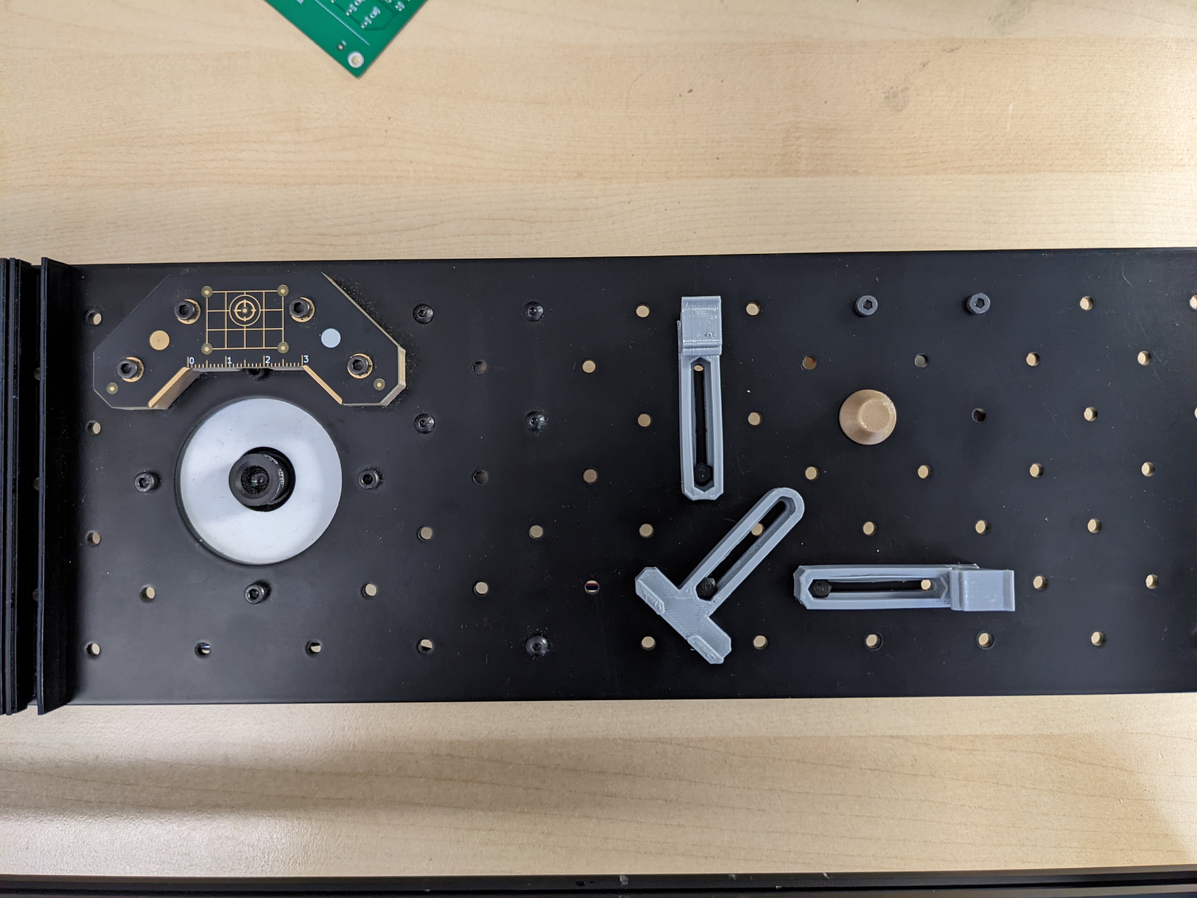
Loosely screw in the universal mounting components in the following locations:
- Static Board Mount positioned diagonally, screwed into B28
- Dynamic Board Mount positioned vertically, screwed into D28
- Dynamic Board Mount positioned horizontally, screwed into B30
- Board Support placed in E31
-
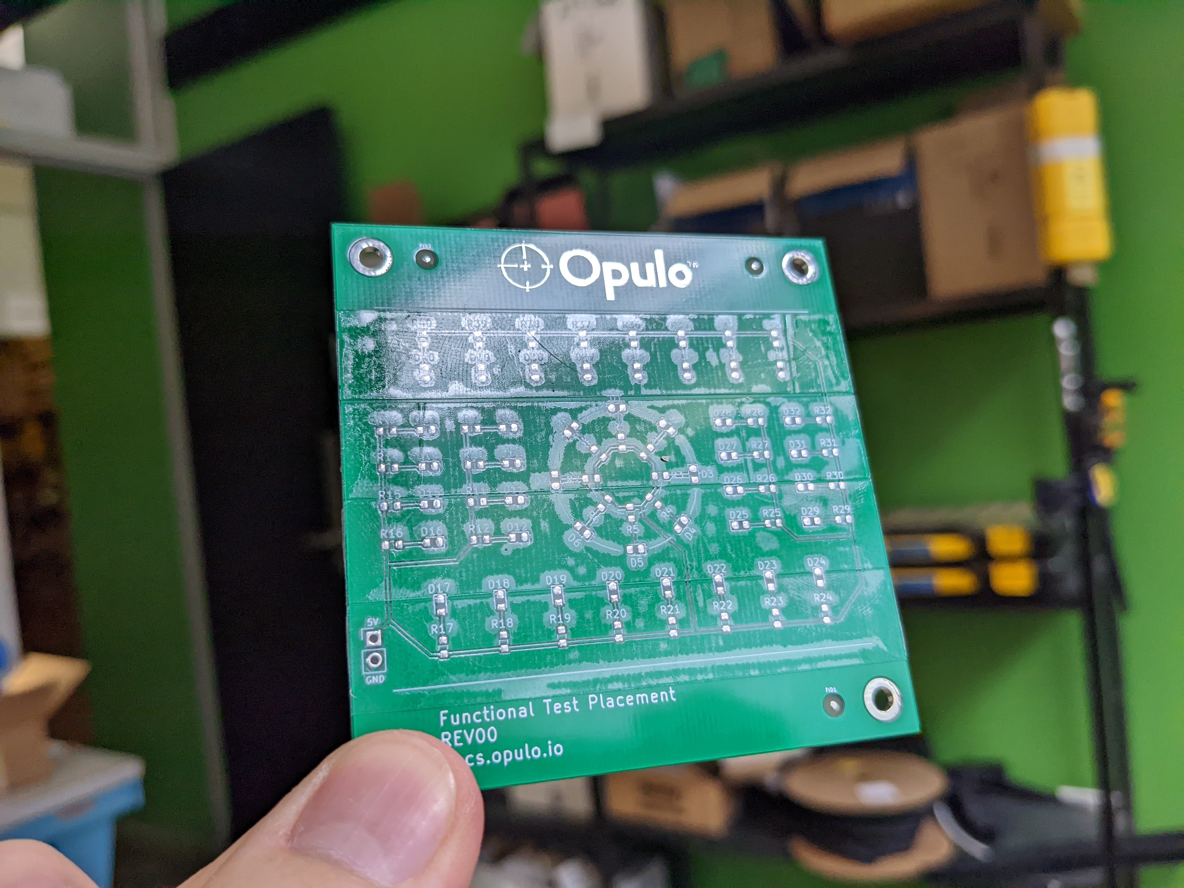
Cut strips of double-sided tape and apply them to the top of the FTP board. Do not cover the fiducial markers, but make sure that each of the pads are covered by tape. The double-sided tape lets the components stick to the board so that you can do a "mock" run of a placement job without dealing with solder paste.
-
Place the FTP board in the holders and push them so that they're snug against the sides of the board. The top edge of the board should line up with the ridge in the dynamic board mount's tab.
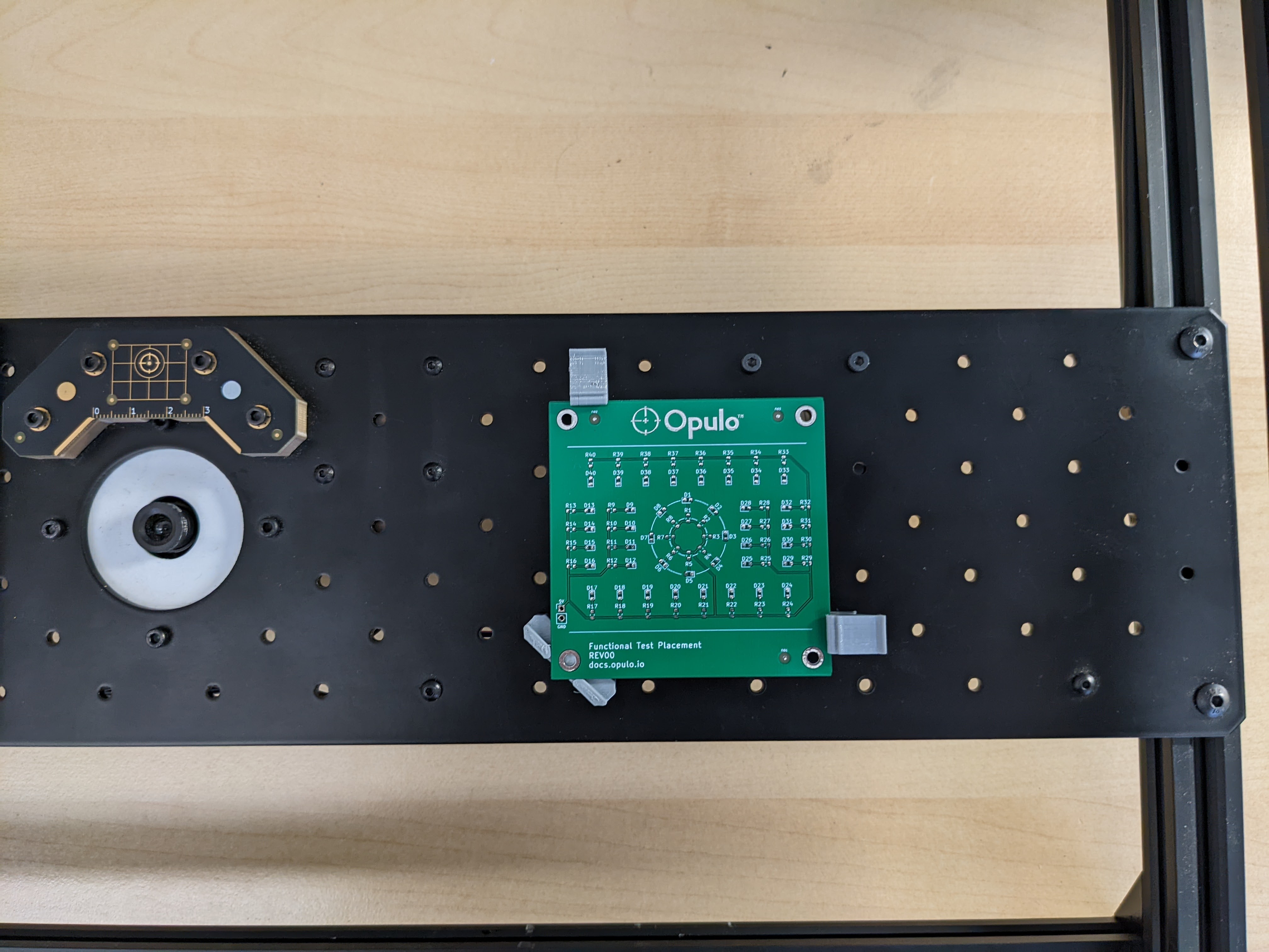
-
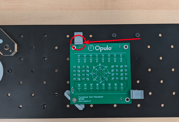
Tighten down the holders. You shouldn't be able to move the board except by pressing on the tab holding it in place.
-
If you installed your holders in this location, the bottom left corner of your FTP board should be located around
X328, Y94.
Finding the FTP Location
The next step is to set the physical location of the FTP board in OpenPNP. You'll start by setting an approximate location and then fine tune the location using vision. Once the location is set, you can run the job to pick and place components. You'll likely need to go through these steps a few times to tune the settings.
-
Navigate to the
Jobtab in the top-right pane.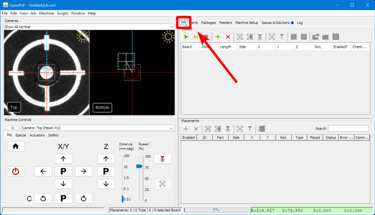
-
In the bottom-right pane, you'll see the
Placementspanel. Find the three elements with the IDs:FID1,FID2, andFID3. You can sort the list byPartto find them easily.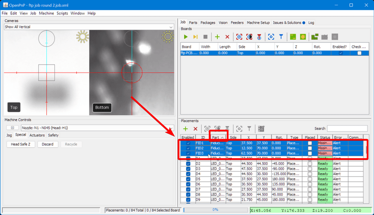
-
For each of the three elements, go to the
Typecolumn, select where it saysPlacementand switch it toFiducial. This tells OpenPnP that these three elements on the board are not components to be picked and placed, but fiducials to be scanned.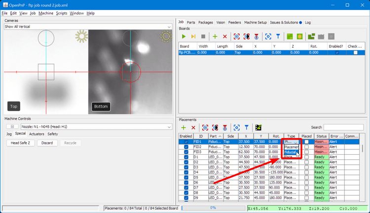
-
Back in the top-right pane, double-click on the
XandYvalues of0.000and change them toX328andY94respectively. This will be the rough location of the bottom-left corner of the FTP board.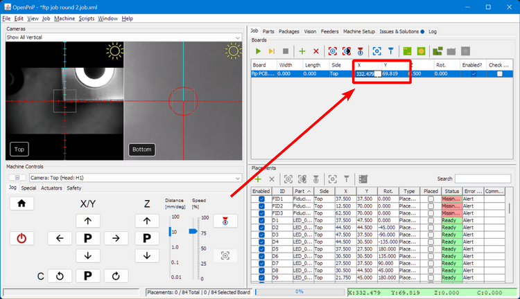
-
Get the Z axis coordinate used when setting up the feeders, subtract
0.10from it, and enter the result into theZcoordinate for the board. Setting theZslightly lower than the actual board height allows the spring-loaded nozzle holder to lightly press components into the board to make them stick.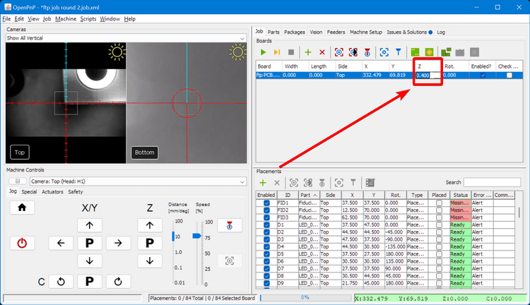
-
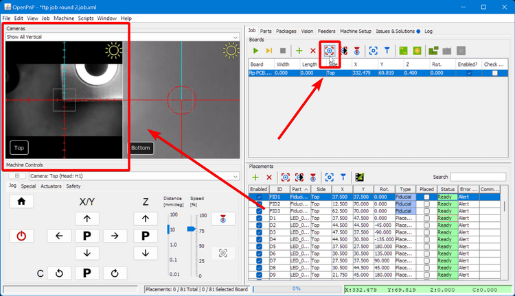
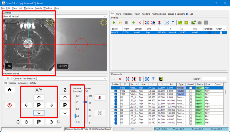
Click the "Position Camera on Board" icon button and check that the center of the camera feed is very roughly lined up with the bottom-left corner of the FTP board.
-
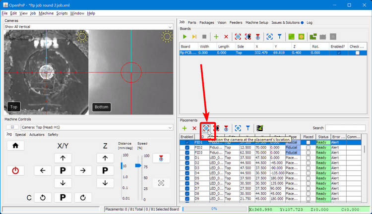
In the lower-right pane, select one of the fiducials to highlight it.

-
Click the "Position Camera" icon button to move the top camera over the fiducial location.
-
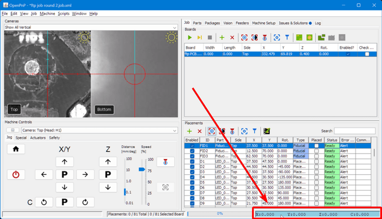
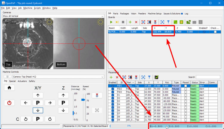
The alignment will probably not be perfect. To fix this, click on the digital readout in the bottom right corner to zero your current position.
-
Then, move the tool head with the Jog buttons until the fiducial is centered in the reticle.
-
Read the relative XY position you've moved your tool head, and add those values to the board's X and Y positions. Do not change the position of the fiducial itself in the lower-right pane list as that will throw off the rest of the placements. Only adjust the location of the board itself, not the components relative to each other.
-
In the lower-right panel, select the other fiducial points in turn, and check their location with the "position camera" icon button.
-
If all the fiducials are close to the reticle center, you're ready to run a fiducial scan to get the exact location of your FTP board. If only the first fiducial is centered, your board is probably rotated (ie the bottom edge is not parallel with the X axis). You can still move on to the fiducial scan, but you may need to manually readjust the board so that it is straighter.
-
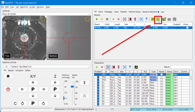
Click on the "Fiducial Scan for Location" button. This will automatically move the camera to each of the fiducial locations and use the camera to try to identify the center of the fiducial. If it can find all three, it will automatically update the position and rotation of the board relative to the LumenPnP gantry.
-
If the fiducial check fails, here are some options for moving forward:
- You might need to rotate the FTP board to be more square to the LumenPnP motion system.
- You may need to adjust your PCB Fiducial Vision Pipeline.
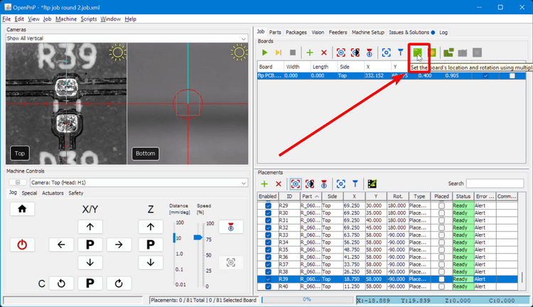
- If you'd prefer, you can also fall back on manually defining the board's location using the "Multiple Placements" icon button.
-
To double-check the board's location, rerun the fiducial scan. It is also useful to select some of the other placement locations and move the camera to them as well to check that the camera is centered between the metal pads.
Placing Components
Home Your Machine
It is crucial that you home your machine before each job. The stepper motors in the LumenPnP de-power after being idle for a while, so rehoming ensures that the machine is aligned and positioned correctly for placement.
-
Make sure you've pulled back the protective tape cover on your feeders and that you have the correct nozzle installed.
-
It's time to place your first component. Press the "Single job step" icon button repeatedly until OpenPnP moves to pick up an LED, check it's orientation over the bottom camera, and then place it on the board.

-
It is normal for your first set of component placements to have some offset errors. We'll address them in the next step.
Next Step
Next, you'll tweak settings to fix placement errors.